Description
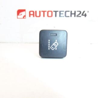
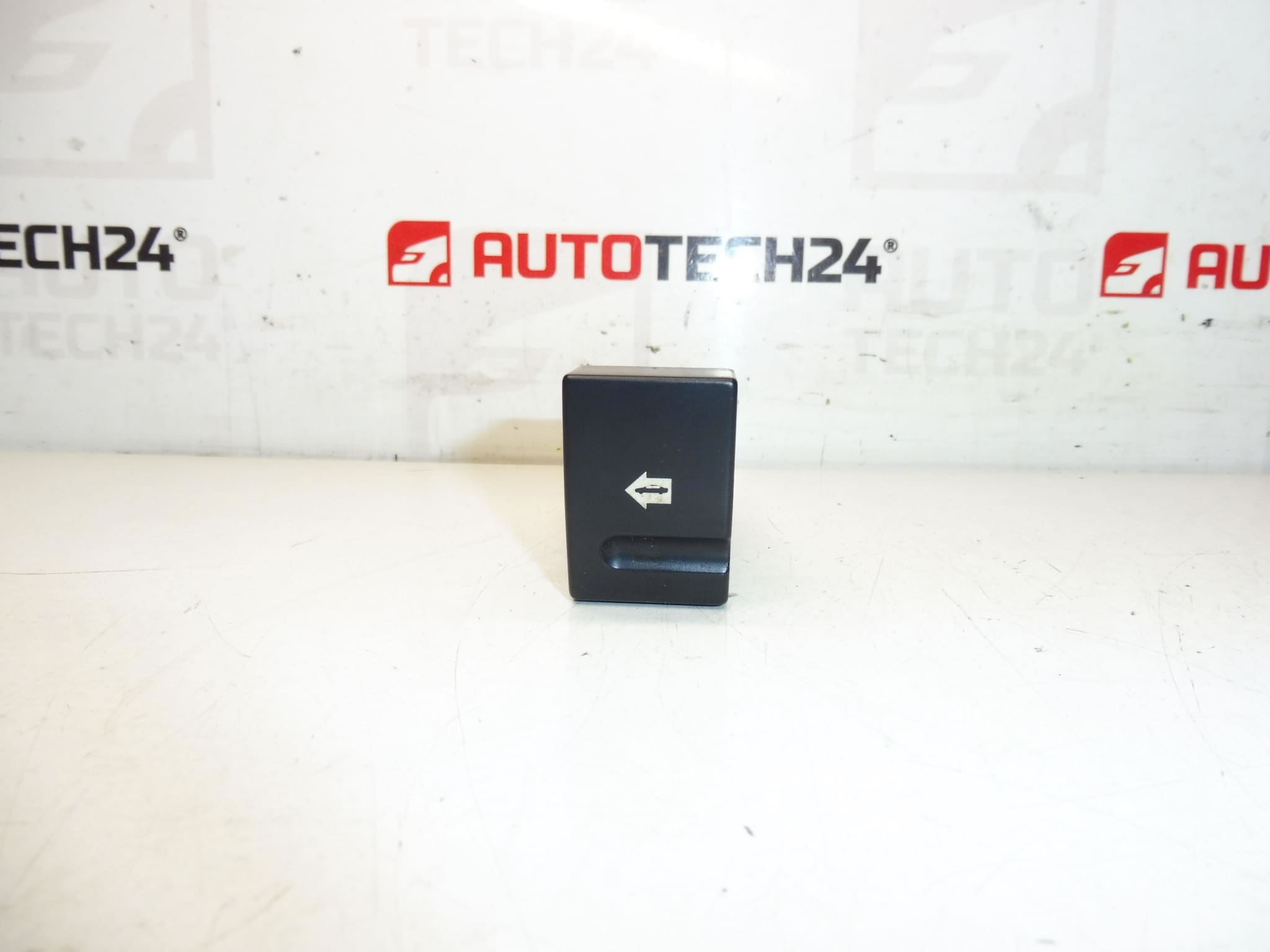
Control Switch for Peugeot 406 Vehicles.
Product Overview
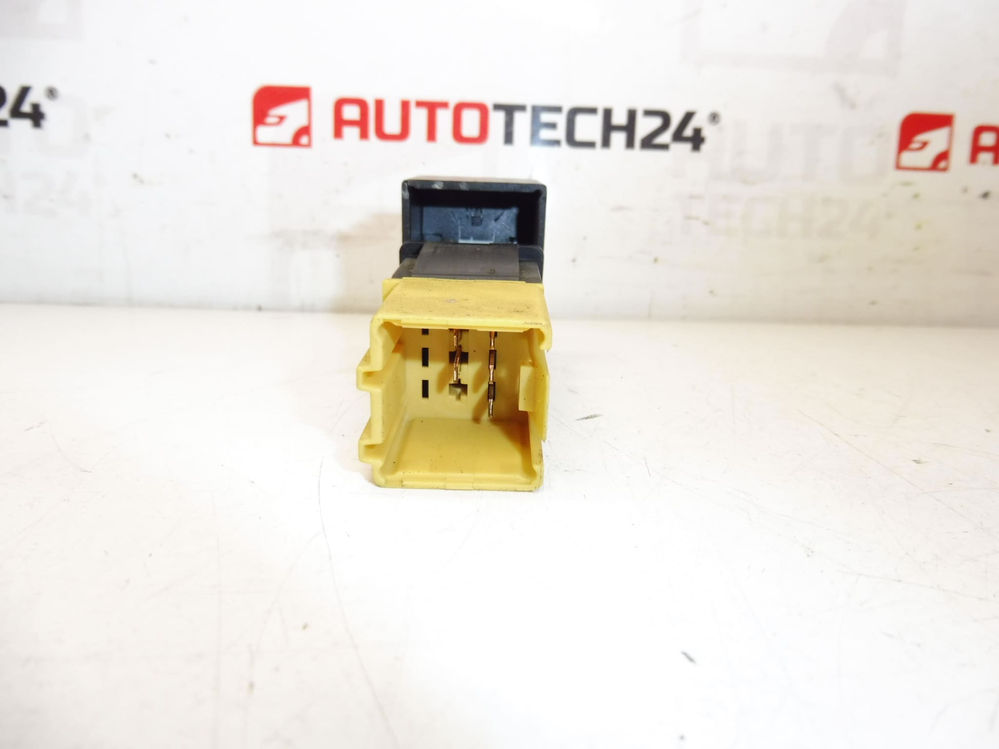
Used control switch designed for Peugeot 406 applications. This original-equipment style switch (product code 6552LW) is a direct replacement for worn or faulty door/console controllers and is commonly sought after by professional technicians and DIY enthusiasts repairing Peugeot electrical systems. The compact unit restores reliable switching functions and helps eliminate intermittent faults caused by degraded contacts or broken actuators.
Benefits And Key Features
– Direct-fit replacement for vehicles using part number 6552LW.
– Restores proper operation of the associated door/console functions (central locking and other electrical controls when applicable).
– Economical solution for extending vehicle service life without modifying wiring or mounts.
– Supplied as a used genuine part from the Stellantis/Peugeot parts family.
Technical Information
- Manufacturer: Peugeot (Stellantis)
- Model: Peugeot 406
- Product Codes: 6552LW
- Additional Numbers: NFP
Compatibility And Fitment Notes
The switch is intended primarily for Peugeot 406 applications that use the 6552LW part code. Always match the part code on the unit to the vehicle’s existing component to confirm fitment. Fitment may vary by production year and trim level; the part is commonly used where original equipment switches have the same connector and mounting arrangement.
Replacement Procedure
1) Prepare the vehicle: Park on a level surface, engage the parking brake and remove the ignition key.
2) Safety first: Disconnect the negative battery terminal to avoid short circuits and accidental actuator operation.
3) Access the switch: Remove the relevant interior trim (door card or lower dash panel) using appropriate trim tools to avoid damage to clips and panels.
4) Disconnect the electrical connector and any retaining clips or screws securing the switch.
5) Install the replacement: Fit the new switch, secure fasteners, reconnect the wiring harness and reassemble trim in reverse order.
6) Test operation: Reconnect the battery and verify all related functions (locking, unlocking, and any auxiliary features) operate correctly before finishing.
Recommended Tools And Tips
Use plastic trim removal tools to prevent scratching panels. A small Torx or Phillips driver may be required depending on vehicle trim. Clean connector pins and apply a contact protector if corrosion is present. Ensure connectors are fully seated and locking tabs engaged to avoid intermittent faults.
Why The Part Fails Most Often
Common failure causes include internal contact wear from frequent use, moisture ingress leading to corrosion, mechanical breakage of plastic components or actuator levers, and degraded solder joints from thermal cycling. Symptoms usually start as intermittent operation, sticking switches, or complete loss of the affected function.
Service Life And Maintenance
Life expectancy depends on usage and environment; many units last well over a decade in normal conditions, but coastal or high-humidity environments accelerate corrosion and wear. Regular inspection and keeping door seals in good condition will help prolong switch life.
Installation Recommendation
Perform installation in a clean, dry workspace. If connector terminals are corroded, address the corrosion before fitting the new switch. After installation, verify all related electrical systems function correctly and perform a final visual check of trim fitment and fastener security.