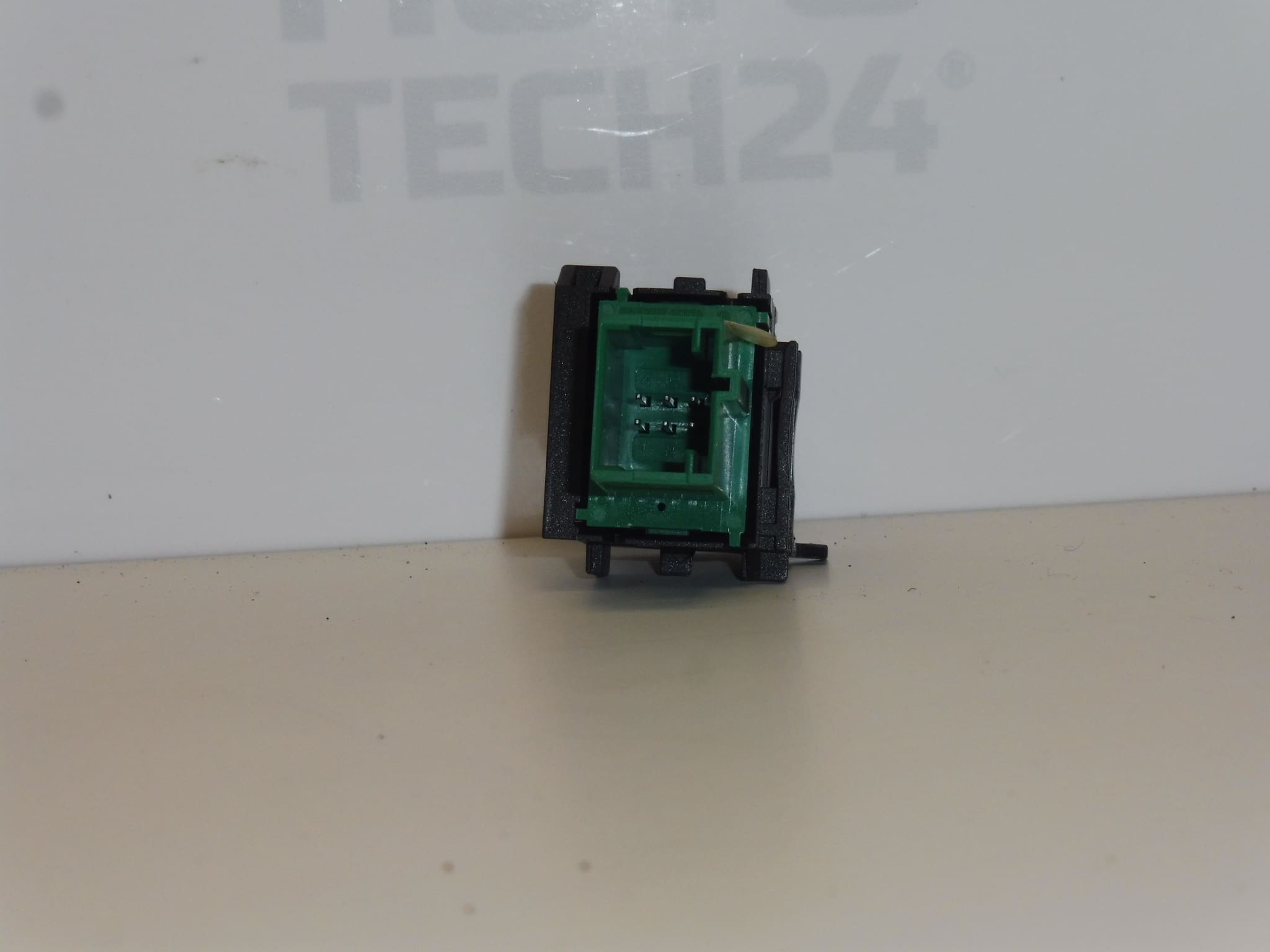
Description
Lane keeping assist control for CITROEN, PEUGEOT and other Stellantis models
Part Description
This used lane keeping assist control, bearing the numbers 9817735877 and 98177358ZD, is designed to operate the vehicle’s corresponding driver assistance function. It is a control element, not the system’s sensor or camera itself. Replacing a faulty or mechanically damaged control with a used part is a cost-effective alternative to buying a new one.
When selecting a part, compare the product numbers, control design, connector and mounting points with the existing part. Matching the model name alone is not sufficient, as the design may depend on the vehicle’s equipment.
Technical Information
- Manufacturer: not specified; the supplied information lists the designation Stellantis CITROEN PEUGEOT.
- Model: Citroën Berlingo K9, FIAT DOBLO III, OPEL COMBO E K9, PEUGEOT RIFTER, Toyota ProAce City.
- Other numbers: not specified.
- Part type: lane keeping assist control.
- Category: electrical components – other controls and switches.
- Condition: used part.
The models are taken from the supplied labels. Model years, engine types and exact equipment variants are not specified in the supplied information.
Product Codes
- Product codes: 9817735877, 98177358ZD.
Use both designations when searching for a replacement control and comparing it with the numbers on the original part.
Installation Recommendations
The following general procedure applies to this type of electrical control. The exact access, removal and function-check procedure depends on the specific model and vehicle configuration. The supplied information does not include model-specific installation instructions.
1) Before installation
- Compare the markings on the old and replacement parts, the shape of the front section, symbols, connector, contacts and mounting hardware.
- Inspect the used control: check for cracks, damaged clips, bent contacts, corrosion and signs of water ingress.
- Make sure the control moves without sticking. Smooth mechanical operation alone does not confirm electrical functionality.
- Before replacing the part, rule out any obvious damage to the connector or wiring. The control itself may not be the cause of an inoperative assistance system.
2) Tools and materials required
- Plastic trim removal tools for gently releasing trim panels.
- Standard hand tools suitable for the fasteners used.
- A flashlight, soft protective mat and clean cloth.
- If needed, a product suitable for cleaning electrical contacts; use it according to the manufacturer’s instructions and do not spray it inside the control without careful consideration.
3) Step-by-step installation procedure
- Park the vehicle safely, secure it against movement and switch off the ignition.
- Follow the vehicle-specific service procedure to allow the electrical systems to enter sleep mode and disconnect the power supply as prescribed.
- Determine how the control is mounted and how to access it. Do not force covers off without checking the position of the clips or screws.
- If access requires removing trim, carefully release it using suitable tools and protect visible surfaces from scratches.
- Release the original control’s fasteners and pull it out only far enough to access the connector. Do not stretch the wiring.
- Unlock the connector and disconnect it by pulling on its housing, not on the wires.
- Inspect the connector and accessible wiring. If corrosion, overheating or damage is found, address the cause of the fault first.
- Compare the two controls again. If the connector, its keying or the mounting points do not match, do not continue by forcing them to fit.
- Connect the replacement control and make sure the connector is properly secured. Route the wiring so that it is neither pinched nor stretched.
- Fit the control in place, secure it using the original method and reinstall any covers that were removed. Restore the power supply according to the vehicle manufacturer’s procedure.
4) Post-installation checks and function verification
- Check that the control is firmly seated, the trim panels fit correctly and the control moves freely.
- After switching on the ignition, check its response to operation as described in the vehicle’s manual and confirm any relevant indicator.
- If a test drive is required to check the system, carry it out safely in accordance with the manufacturer’s instructions. Do not deliberately cause the vehicle to leave its lane in a hazardous manner.
- If the fault persists, continue by diagnosing the power supply, wiring and relevant system; do not automatically assume that the control is faulty.
5) Common installation mistakes and how to avoid them
- Choosing by appearance alone: always compare the part markings, connector and mounting points as well.
- Breaking the clips: first determine how they are released and use appropriate force.
- Pulling on the wires: disconnect the connector only after unlocking it, and hold it by its housing.
- Connector not fully engaged or wiring harness pinched: check that the connector is secured and the wiring is routed correctly before refitting the trim.
- Working on a live circuit: follow the manufacturer’s procedure for safely disconnecting and reconnecting the power supply.
Reasons Why the Part May Be Damaged
The following are general possible causes of damage for this type of control; they do not describe any faults in the item for sale:
- Mechanical wear of the control mechanism due to prolonged use.
- Excessive force or impact, which can damage the button, control housing or its mounting points.
- Ingress of liquids and dirt, which can cause sticking or damage to the electrical contacts.
- Moisture and connector corrosion, which can cause an unreliable electrical connection.
- Rough removal, particularly prying with the wrong tool, breaking clips and pulling on the wiring.