Description
Part description
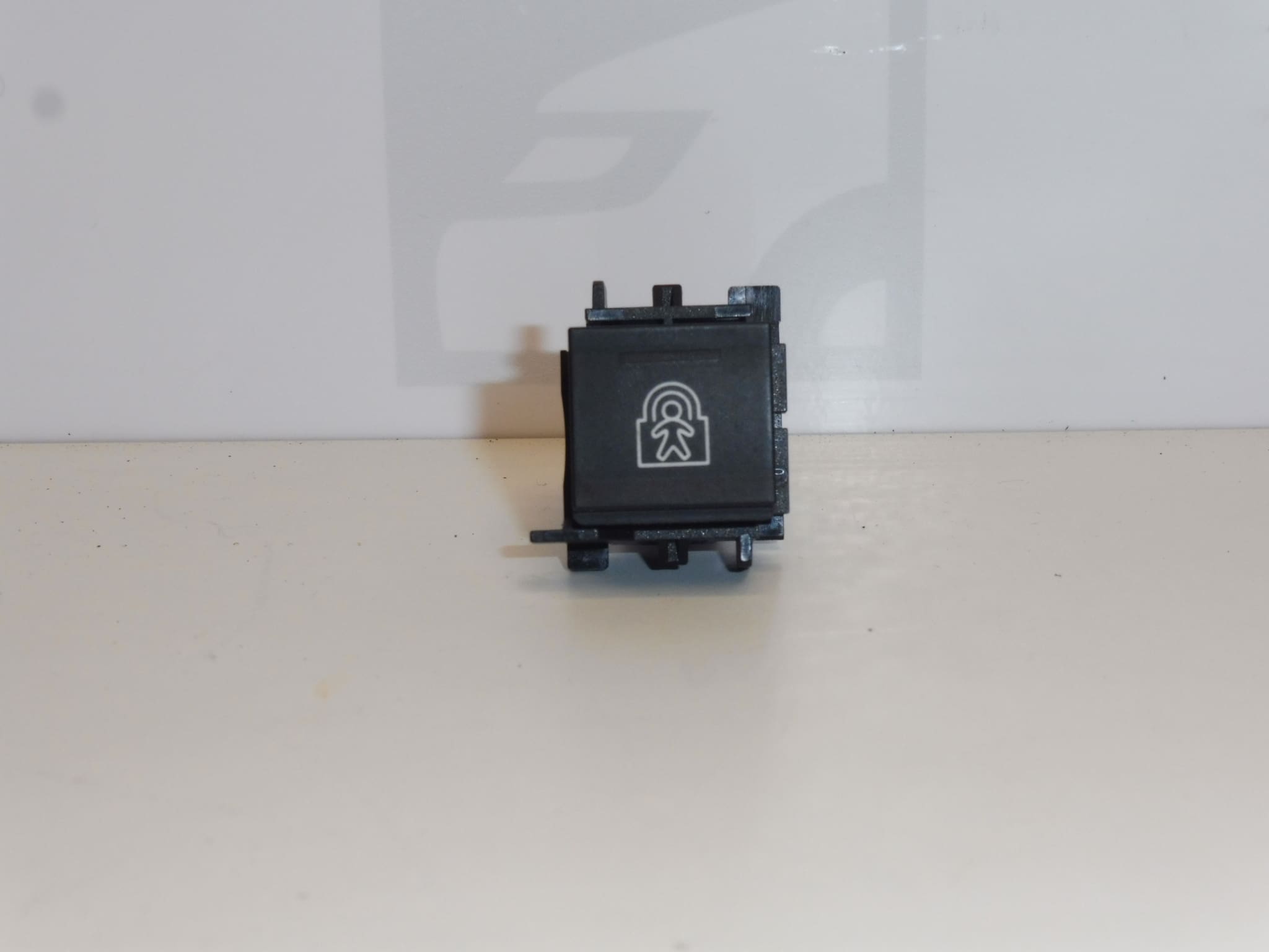
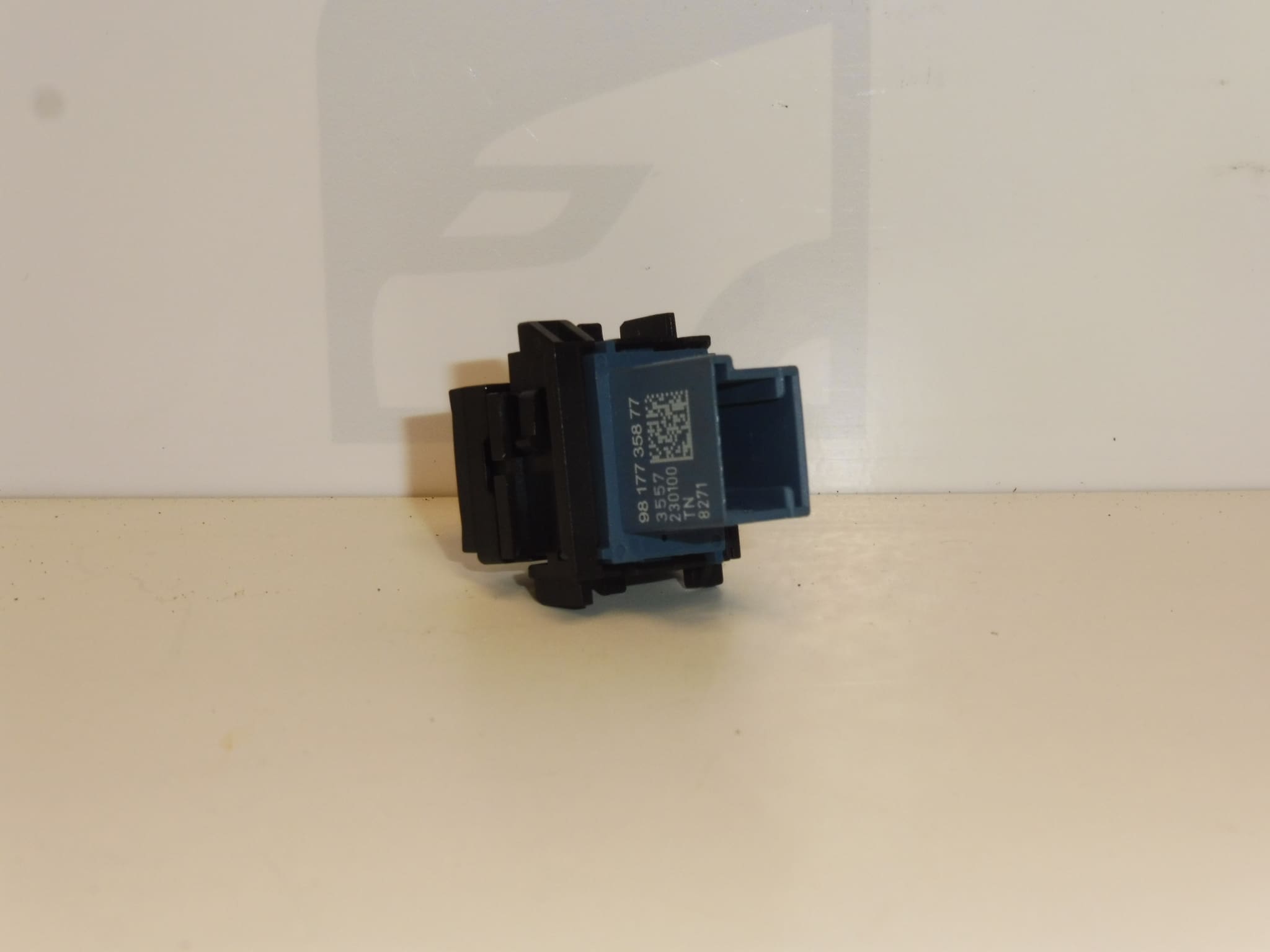
Used Citroën Peugeot 98177358ZD control switch from the electrical controls and switches category. It is a suitable choice when looking for a replacement part based on the marking on the original part. The source materials also list the number 9817735877.
The part is listed for the Citroën Berlingo K9, FIAT DOBLO III, OPEL COMBO E K9, PEUGEOT RIFTER, and Toyota ProAce City models. The specific controlled function and equipment variant are not specified, so when selecting a part, compare the product number, control switch design, connector, and mounting with the original part. The model name alone may not be enough to determine the correct version.
Technical information
- Manufacturer: not specified; the source materials list the designation Stellantis CITROEN PEUGEOT.
- Model: Citroën Berlingo K9 | FIAT DOBLO III | OPEL COMBO E K9 | PEUGEOT RIFTER | Toyota ProAce City.
- Part type: electrical control switch; category Other controls and switches.
- Condition: used part.
- Main product number: 98177358ZD.
- Additional numbers: 9817735877.
- Specific function, location, and connector design: not specified.
Product codes
- Product codes: 98177358ZD, 9817735877.
When looking for a replacement, compare these markings with the number on the original control switch. The fact that both numbers are listed in the source materials does not in itself confirm that all variants are interchangeable.
Installation recommendations
The following procedure is general guidance for replacing an electrical control switch. The exact steps, access to the part, and any subsequent setup depend on the specific model and vehicle configuration. The source materials do not include installation instructions for this part.
1) Before installation
- Compare the markings on the original and replacement parts, the shape of the housing, controls, mounting, and connector, including its mechanical keying.
- Inspect the used part, especially for cracks, damaged clips, loose parts, the condition of the contacts, and any signs of moisture or overheating.
- Check whether the fault may be caused by the wiring, connector, or power supply. Replacing the control switch will not resolve such a fault.
2) Tools and materials required
- Hand tools suitable for the actual vehicle fasteners.
- Plastic trim removal tools if surrounding trim needs to be removed.
- A flashlight, a clean cloth, and, if necessary, a product suitable for electrical contacts and surrounding materials.
- A multimeter or diagnostic equipment, as needed, to check for an electrical fault.
3) Step-by-step installation procedure
- Park the vehicle safely, secure it against movement, and switch off the ignition and electrical accessories.
- Follow the manufacturer’s service procedure to allow the electronics to enter a sleep state, and disconnect the battery as specified before disconnecting any electrical connections.
- Document the original position of the control switch and the wiring route, for example by taking a photo.
- If access requires removing a cover or trim panel, carefully release its fasteners. Do not force tools into areas where the clips are not known.
- Release the original control switch’s mounting and expose the connector without pulling on the wires.
- Release the connector lock and disconnect it by pulling on the connector housing, not the wires.
- Inspect the contacts and wiring. Address any corrosion, looseness, or heat damage before connecting the replacement part.
- Compare the two control switches again. Connect the matching connector without forcing it, and check that its locking tab is properly engaged.
- Secure the control switch as originally installed, route the wiring without pinching it, and reinstall any covers or trim panels that were removed.
- Reconnect the battery according to the manufacturer’s instructions and carry out any required restoration of functions after disconnecting it.
4) Post-installation checks and function testing
First, with the vehicle stationary, test all functions of the relevant control switch. Check that the controls operate smoothly, the switch is firmly seated, and the controlled system responds correctly. If a function needs to be tested while driving, take a short, safe test drive only after successfully completing the stationary checks. Stop the test if you notice unusual behavior, an odor, or heating.
5) Most common installation mistakes and how to avoid them
- Choosing based on appearance alone: also compare the numbers, connector, and mounting.
- Breaking the clips: first determine how they are secured and do not use excessive force.
- Connector not fully engaged or wires pinched: check the connector lock and wiring route before closing the trim.
- Overlooking an electrical circuit fault: if problems persist, check the power supply, connections, and related system instead of repeatedly replacing the control switch.
Reasons why the part gets damaged
Common causes of damage to electrical controls and switches in general include:
- Mechanical wear of the controls and internal contacts due to frequent use.
- Ingress of moisture, spilled liquids, or dirt, which can interfere with contact and the movement of the mechanism.
- Excessive force when operating the control or careless removal, leading to cracks in the housing or mounting points.
- Loose or corroded electrical connections, which can cause interruptions and overheating.
- Wiring or power supply faults, which can affect operation or damage the electrical components of the control switch.
These are general causes for this type of part, not a description of the condition of the item offered.