Description
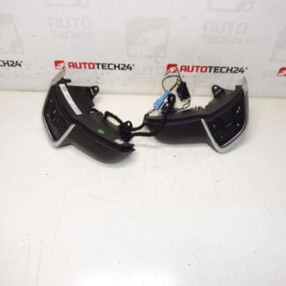
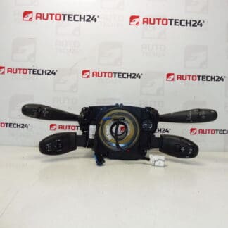
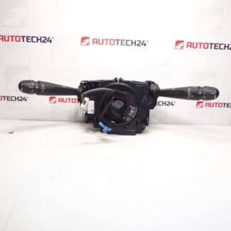
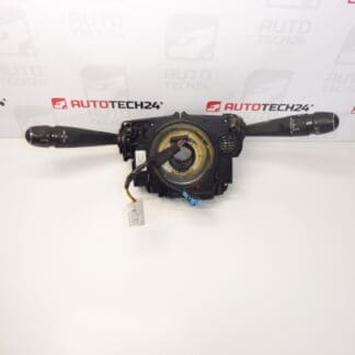
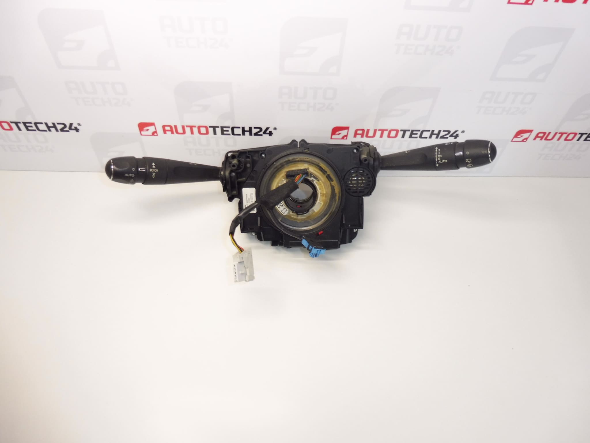
COM2008P steering wheel controls, levers for Citroen C4 II, Peugeot 508, DS4 and DS5 cars
They control the lights, fog lights, front and rear wipers, blinkers, horn, on-board computer
Part description
The used controllers under the steering wheel COM2008P combine the control of lighting, turn signals, wipers and other listed functions into a single unit. They are intended as a spare part in the event of a malfunction of the original levers, for example if a function does not respond, works intermittently or the controller is mechanically damaged. Before replacing it, it is important to distinguish between a fault in the levers themselves and a problem in the wiring or connected electrical circuit.
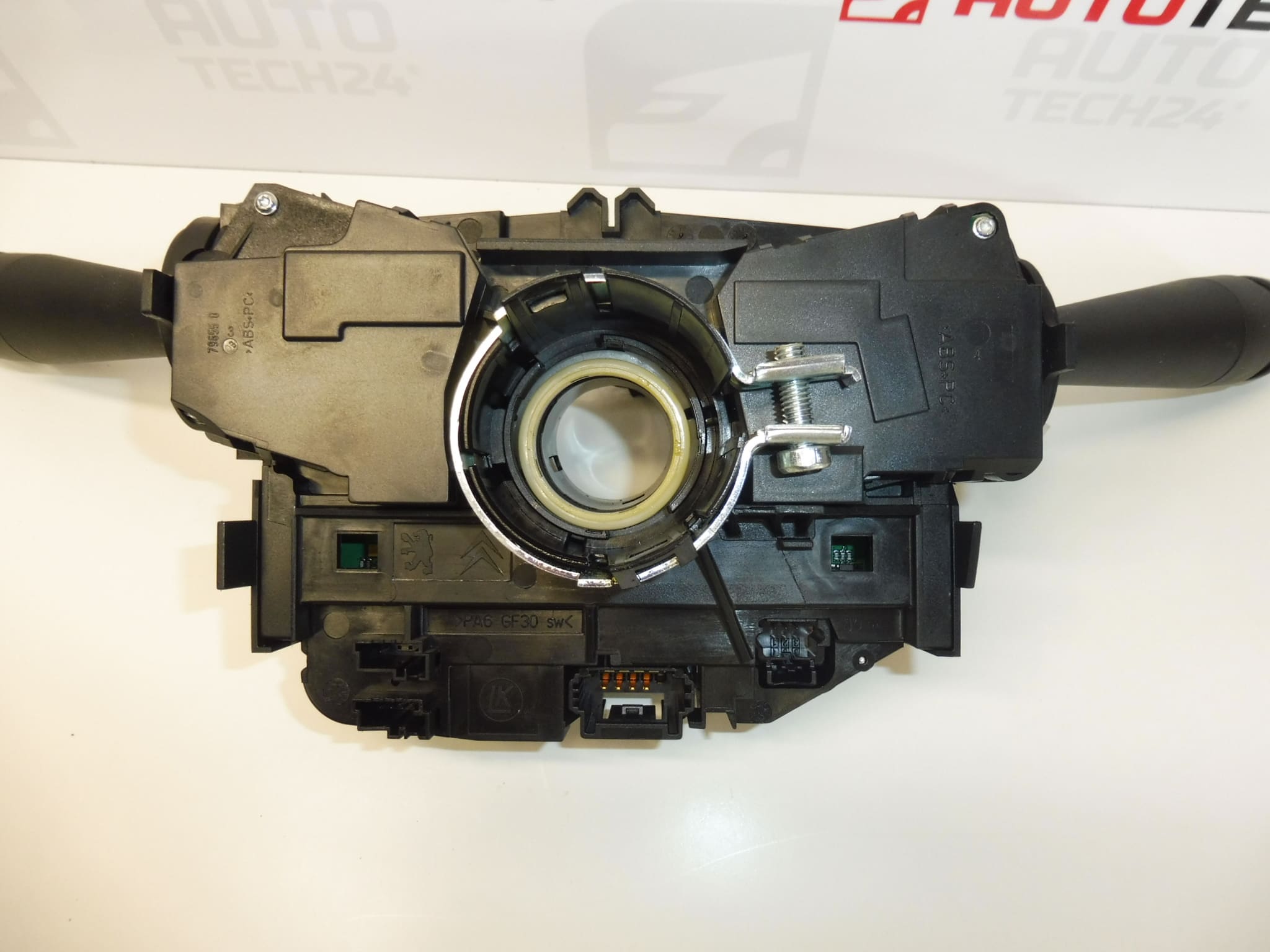
When looking for a replacement, the designations 96759252XT and 6243C6 are essential. Compare them with the original part together with the design of the connectors, the attachment and the range of controlled functions. The same car model does not necessarily mean the same design of the controls. A correctly selected used part is a practical alternative to buying a new unit.
Technical information
- Manufacturer: not specified
- Model: Citroen C4 II, DS4, DS5, Peugeot 508 (names according to supplied labels)
- Other numbers: not specified
- Type designation: COM2008P
- Type of part: controls under the steering wheel, lever control unit
- Controlled functions: lights, fog lights, front and rear wipers, indicators, horn and on-board computer
- Condition: used car part
- Years and engines: not specified
Product codes
- Product codes: 96759252XT, 6243C6
- Drivers Designation: COM2008P
Compare the numbers with the designation of the disassembled unit. In addition to the numbers, also check the correspondence of the controls and their functions; the similar appearance of the levers alone is not enough.
Installation recommendations
In general, this type of part applies: the following procedure is indicative for replacing the electric controls under the steering wheel. The exact disassembly method, safety measures and possible diagnostic actions depend on the specific model and version of the car. The documents do not specify whether it is necessary to remove the steering wheel or interfere with the airbag system when replacing this part.
1) Before assembly
- Verify that the drivers are indeed the cause of the problem, and not a damaged wire, connector, or other part of the circuit in question.
- Compare the product numbers, COM2008P designation, number and shape of connectors, mounts, lever symbols and range of functions with the old piece.
- Inspect the used part: look for cracks, damaged latches, bent contacts, corrosion and traces of moisture.
- Gently test the movement of the levers and controls. They should not snag or require excessive force.
- Prepare the service procedure for the given car, especially the rules for disconnecting the battery and any work near the airbag.
2) Necessary tools and materials
- Common hand tools corresponding to the fasteners used.
- Plastic tools for careful disassembly of covers and suitable lighting.
- Tools for marking connectors, container for connecting material and a clean, lint-free cloth.
- According to the service procedure, diagnostic equipment suitable for a specific car.
3) Step-by-step assembly procedure
- Secure the vehicle securely against movement, switch off the appliances and switch off the ignition.
- Follow the manufacturer’s procedure for switching the electronics to idle state and disconnecting the battery. Wait the prescribed time before continuing to work.
- Access the drivers by removing the necessary covers according to the service documentation. Release the plastic latches without force.
- If access requires removal of the steering wheel or airbag, proceed only with appropriate knowledge and according to the manufacturer’s procedure. Do not measure the airbag connectors with a regular multimeter or tester.
- Before disconnecting, note the wiring route and the position of the connectors. Release their fuses and disconnect them by pulling on the body of the connector, not the wires.
- Unfasten the original control unit and carefully remove it. Avoid damage to surrounding cabling and downstream components.
- Compare both parts side by side. Check the seating surfaces, mounts and connectors; remove any dirt in the surroundings without getting it inside the controls.
- Place the replacement unit in the correct position without prying and secure it according to the service procedure. Tighten the fasteners according to the manufacturer’s documentation.
- Connect the connectors until the fuses are secured. Run the cabling along the original route so that it is not stretched, pinched or in contact with moving parts.
- Reassemble the removed parts and covers. Connect the battery according to the manufacturer’s procedure and perform any prescribed initialization or diagnostic checks.
-
4) Post-assembly checks and function verification
First, while the vehicle is stationary, check the lights, fog lights, turn signals, horn, on-board computer control and front and rear wipers according to the vehicle’s equipment. Do not test the wipers on dry or frozen glass. Check the operation of the levers, the correct reactions of the individual positions and any warning messages. Carry out a short test drive only after a successful check of the safety-relevant functions; test the controls while driving only if the traffic situation safely allows it.
5) The most common assembly mistakes and how to avoid them
- Choose only according to appearance: compare codes, connectors and functional design.
- Forcibly disconnecting the connectors: first release their fuses, do not pull on the cables.
- Pinched wiring: check for routing and looseness before installing covers.
- Extended fixings: follow the service procedure to prevent the plastic handles from cracking.
- Omission of the safety procedure: respect the rules for disconnecting the battery and possible handling of the airbag.
- Incomplete testing: test all features listed, not just the one that changed the original part.
Reasons why the part is damaged
For stick controls of this type, the following influences tend to be the general causes of damage. It is not about the ascertained condition or history of the offered piece.
- Mechanical wear and tear: repeated use stresses the switching mechanisms and lever detents.
- Wear or contamination of contacts: can lead to intermittent or unreliable control of functions.
- Moisture and dirt: promote corrosion of the contacts and can disrupt the operation of the mechanism.
- Excessive force or impact: there is a risk of breaking the lever, damaging the cover or fixing points.
- Improper disassembly and assembly: Forceful prying, pulling on wires or incorrect seating can damage an otherwise functional part.