Description
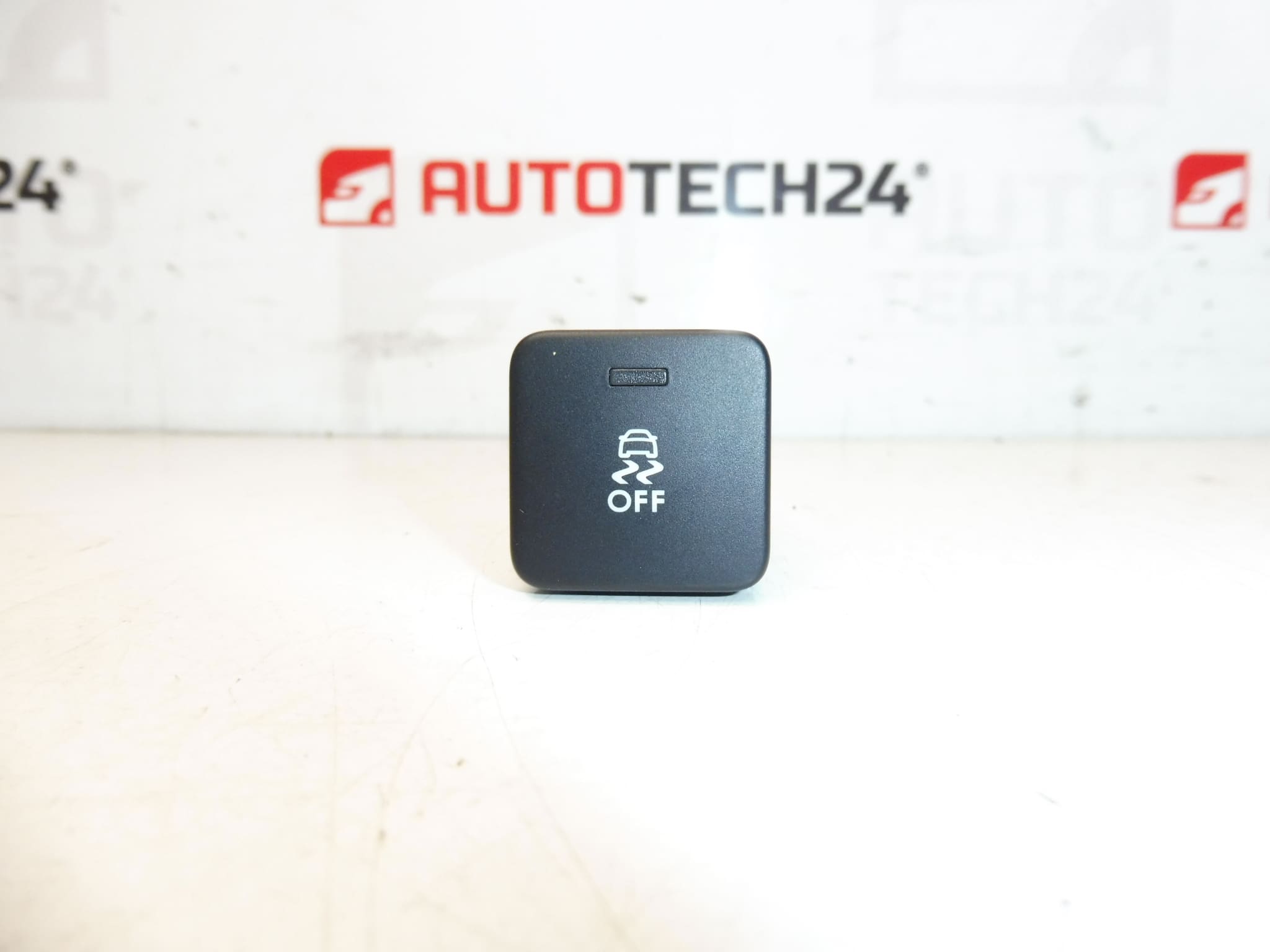
ESP Controller For Citroën C4 II And DS4
Overview
This ESP controller (stalk/switch) is designed for Citroën C4 II and DS4 vehicles and provides reliable operation of the Electronic Stability Program (ESP/ESC) functions from the driver’s cockpit. It allows the driver to enable or disable stability/traction control functions and communicates with the vehicle’s ABS/ESP network to change settings or acknowledge system states. The part is commonly fitted as an OE-style unit for Stellantis group vehicles (Citroën/Peugeot).
Key Features
- Direct fit for Citroën C4 II (C4 B7) and DS4 models.
- OEM-compatible product codes: 96664234ZD, 454955.
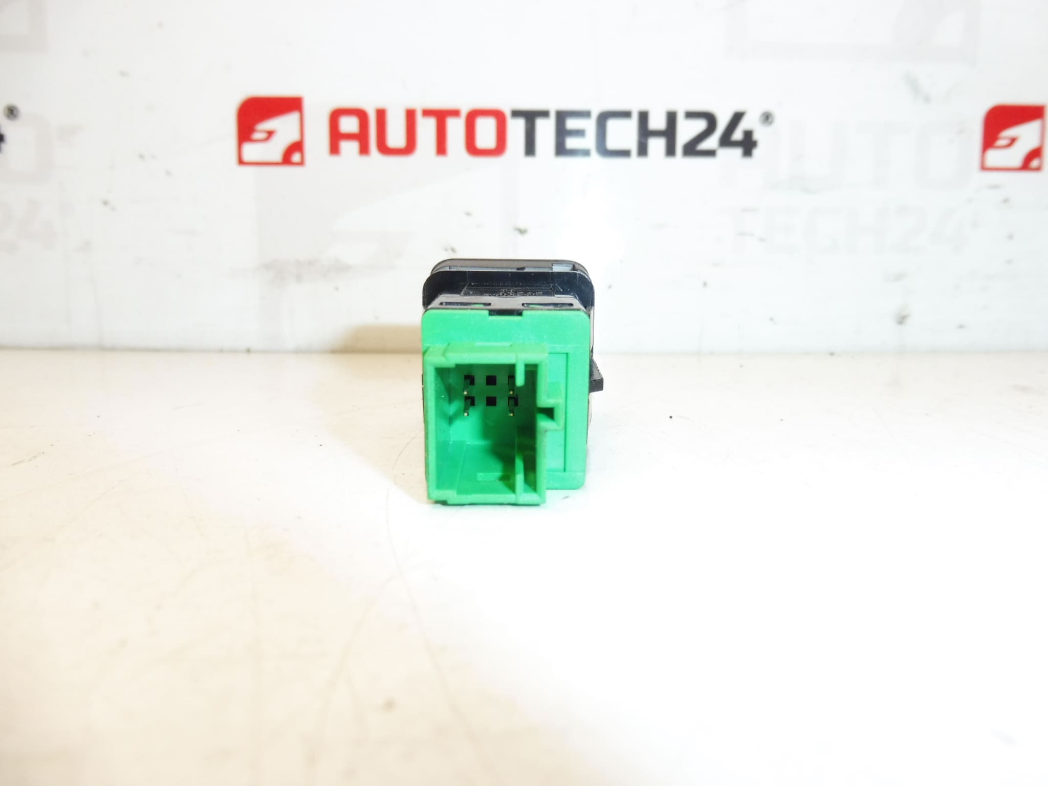
- Simple dashboard-mounted switch with electrical connector to vehicle CAN/ABS network.
- Typical plug-and-play replacement in most cases; diagnostic check recommended after installation.
Technical Information
- Manufacturer: Stellantis
- Model: Citroën C4 II (C4 B7); DS4
- Product Codes: 96664234ZD, 454955
- Additional Numbers: 9664234D, 96664234D, 454955
Compatibility And Fitment
This unit is intended for Citroën C4 II and DS4 models that use the corresponding ESP/traction control switch assembly. Always check the physical connector, mounting orientation and part codes on the original item before ordering to ensure correct fitment.
Common Symptoms Of A Faulty Unit
- ESP/Traction control light illuminated on the dash.
- Switch Unresponsive Or Sticks When Pressed.
- Loss Of Ability To Manually Disable/Enable ESP Functions From The Switch.
- Intermittent Electrical Faults Or Communication Errors With ABS/ESP Module.
Replacement Procedure (General Guide)
- Prepare Vehicle: Park on level ground, engage handbrake, and remove ignition key.
- Safety First: Disconnect the negative battery terminal before starting work to avoid short circuits and to protect vehicle electronics.
- Access: Remove the trim panels surrounding the switch on the dashboard or center console according to the vehicle’s trim removal procedure.
- Disconnect: Release the retaining clips or screws and unplug the electrical connector from the switch.
- Install: Fit the replacement unit, reconnect the electrical connector and secure with the original fasteners and trim pieces.
- Verify: Reconnect the battery, start the vehicle and verify switch function. Clear any stored fault codes with a diagnostic tool and confirm proper communication with the ABS/ESP module.
Installation Recommendations
- Always Disconnect The Battery Before Removing Or Installing The Switch To Prevent Damage To Vehicle Electronics.
- Handle Electrical Connectors Carefully; Avoid Bending Pins Or Contaminating Contacts.
- If Fault Codes Persist After Replacement, Use A Diagnostic Tool To Read/Clear Codes And Verify Communication On The CAN/ABS Network.
- A Dry, Clean Installation Environment Reduces The Risk Of Future Failures Caused By Moisture Or Dirt.
Why The Part Most Commonly Fails
Failure Typically Results From Mechanical Wear, Moisture Ingress, Dirty Or Corroded Connector Pins, Or Internal Electrical Component Degradation Due To Age and Repeated Use. Spilled Liquids On The Dashboard And Frequent Heavy Use Can Accelerate Wear. In some cases, wiring or CAN-bus related faults elsewhere in the vehicle can produce symptoms that mimic a failed switch.
Notes For Mechanics And DIYers
This part is aimed at professional technicians and experienced DIYers. While many replacements are straightforward, diagnosing electrical or network communication faults may require professional diagnostic equipment. After installation, always confirm that the ESP/ABS system shows no residual faults and that the switch behaves as expected during a test drive.