Description
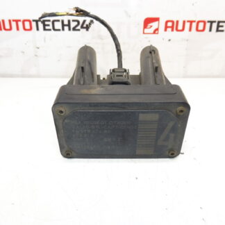
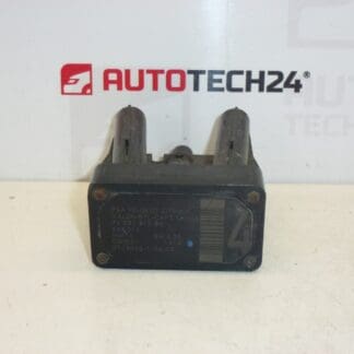
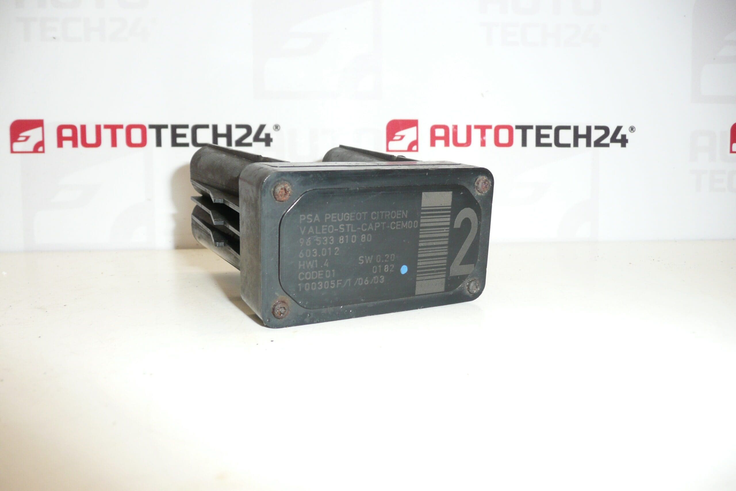
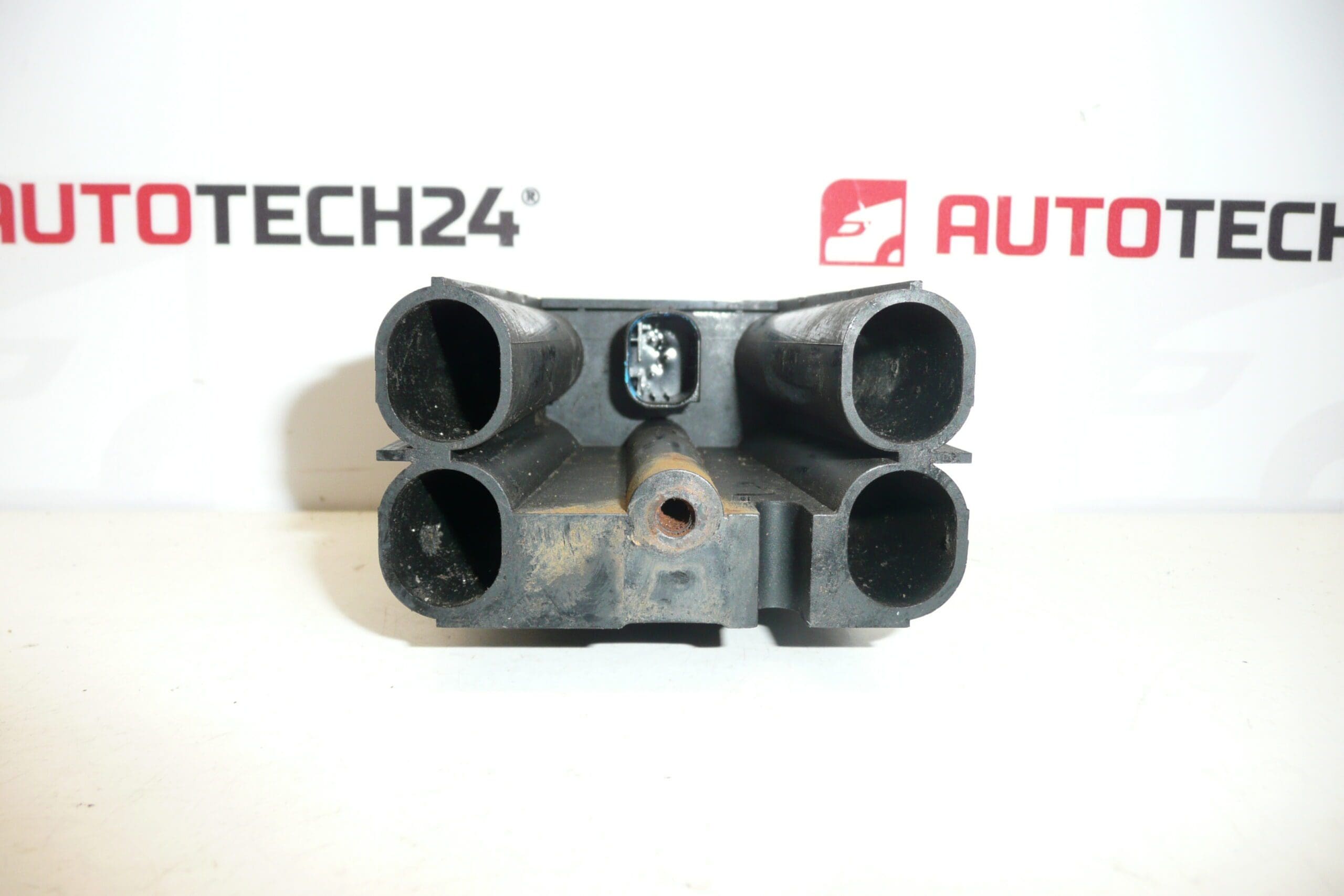
Lane Departure Monitoring AFIL Sensor Number 2 For Citroën And Peugeot Vehicles. A Screw That Secures The Unit To The Wheel Arch May Be Seized — It Needs To Be Drilled Out.
Product Overview
This AFIL (Lane Departure Monitoring) sensor number 2 is a genuine-styled component suitable for selected Citroën and Peugeot models. It monitors lane-keeping and lane-departure functions and communicates with the vehicle’s driver-assistance systems. Supplied under reference numbers commonly searched by workshops and DIYers, the unit is a direct-replacement type designed for fast identification and fitment.
Key Benefits
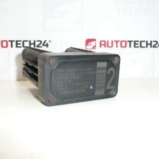
- Direct fit for compatible Citroën and Peugeot models — easy to identify by OEM codes 9653381080 and 6590W1.
- Restores lane-departure monitoring performance when original sensor is faulty or damaged.
- Targeted at professional mechanics and experienced DIY repairers who search by part number.
Technical Information
- Manufacturer: Stellantis (Citroën / Peugeot)
- Model: Citroën C4, Citroën C4 Picasso, Citroën C5, Citroën C5 X7, Citroën C6, Peugeot 308, Peugeot 407
- Product Codes: 9653381080, 6590W1
- Other Numbers: 603.012
Installation Recommendations
Before starting, park the vehicle on level ground and work in a dry, well-lit area. Disconnect the battery when handling electrical connectors. Typical replacement steps:
- Remove the inner wheel-arch liner or access panel to reach the sensor mounting point.
- Disconnect the electrical connector and free any retaining clips or wiring harnesses.
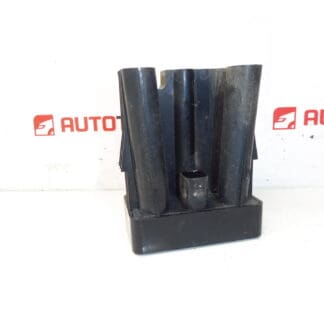
- If the mounting screw is seized (a common issue), drill out the screw carefully and remove the housing from the bracket.
- Install the new sensor, replace any corroded fasteners, reconnect the wiring and secure the wheel-arch liner.
- Reconnect the battery and clear any stored fault codes with a diagnostic tool; check the lane-assist function and perform any required ADAS/ camera recalibration if the vehicle or system requests it.
Use anti-seize or replacement stainless fasteners where appropriate and avoid stressing wiring. If in doubt about calibration, consult a diagnostic specialist — correct alignment ensures reliable lane-detection performance.
Why This Part Commonly Fails
Failures are usually related to environmental and mechanical factors rather than electronic design. Typical causes include:
- Corrosion and water ingress from road salt and moisture leading to connector or housing damage.
- Physical impact from debris or minor collisions that misalign or damage the unit.
- Seized mounting screw(s) due to rust — often requiring drilling out the fastener to remove the old unit.
- Wiring abrasion or connector faults caused by movement of the wheel-arch liner or neglected repairs.
Notes For Buyers
This sensor is commonly searched by its OEM references (9653381080, 6590W1). It is intended for workshops and competent DIY mechanics familiar with ADAS components; correct installation and, where necessary, recalibration will restore proper lane-monitoring function.