Description
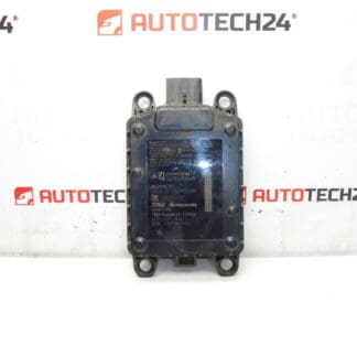
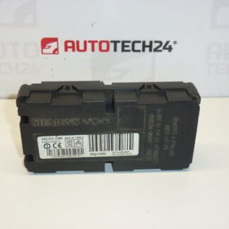
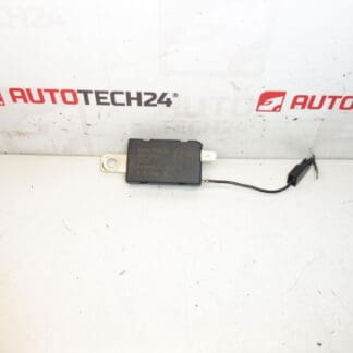
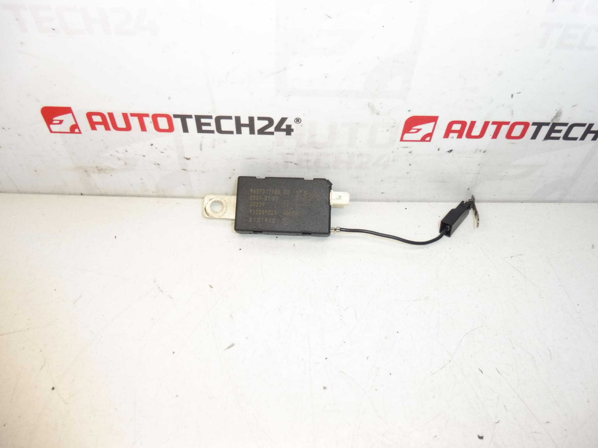
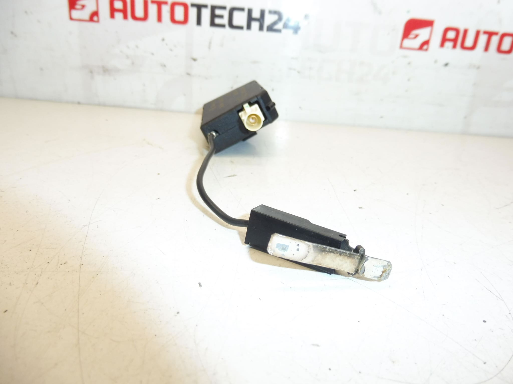
Antenna Amplifier AM/FM1 For Citroën And PEUGEOT Vehicles
Overview
This Antenna Amplifier AM/FM1 is an electrical module designed for Citroën and Peugeot vehicles. It amplifies radio antenna signals to improve AM and FM reception, reduce noise and fading, and support features such as RDS and traffic announcements where fitted. The unit is commonly identified by product codes 9657017980 and 6561JV and is often searched by these numbers by professionals and DIY enthusiasts alike.
Technical Information
- Manufacturer: Stellantis / Citroën / Peugeot
- Model: Citroën C4 Picasso (and other Citroën/Peugeot models using the same amplifier codes)
- Product Codes: 9657017980, 6561JV
- Additional Numbers: NFP
Function And Role
The antenna amplifier boosts weak AM and FM signals received by the vehicle antenna before they reach the head unit. By increasing signal strength and improving signal-to-noise ratio, the amplifier helps maintain clearer reception in fringe areas, reduces static and improves the stability of stereo and RDS data. It sits in the antenna circuit between the aerial mast (or mast feed) and the radio head unit.
Common Failure Modes
Amplifiers like this typically fail due to environmental and electrical causes rather than mechanical wear. The most frequent issues are moisture ingress and corrosion of connectors, water intrusion around the antenna base, deterioration of internal electronic components (electrolytic capacitors), and damage from electrical surges (e.g., during jump-starting or lightning strikes). Faulty cabling or a damaged antenna mast can also make the amplifier appear defective.
Replacement Procedure
Typical replacement steps (general guidance):
- Disconnect the negative battery terminal before starting work to prevent short circuits.
- Locate the amplifier. Depending on model it may be mounted in the luggage compartment, behind trim panels, under the dash or near the antenna base—consult vehicle repair manual for exact location.
- Remove any trim or covers to access the unit. Keep fasteners and clips for reinstallation.
- Carefully disconnect the antenna coax connector(s) and electrical plug(s). Inspect connectors for corrosion or damage.
- Unbolt or unclip the amplifier and replace with the new unit, ensuring correct orientation and secure mounting.
- Reconnect connectors, reassemble trim, reconnect the battery and test AM/FM reception and any related radio features (RDS/AF/TP) to confirm correct operation.
Installation Recommendations
- Always Disconnect The Battery Before Removing The Unit To Avoid Electrical Damage.
- Clean Connectors And Apply A Light Film Of Dielectric Grease To Prevent Future Corrosion.
- Confirm That Coaxial Connectors Are Properly Seated And That The Antenna Mast And Cabling Are Intact.
- When Reassembling Trim, Ensure No Pinching Or Sharp Bends Are Placed On Coax Leads.
- After Installation, Perform A Reception Check Across Bands And Verify Any Radio-Related Features.
Why This Part Fails Most Often
Moisture And Corrosion Around The Antenna Or Connector Areas Is The Leading Cause Of Failure. Water Ingress At The Antenna Base Or Damaged Seals Allows Corrosion To Develop On Coax And Electrical Contacts, Leading To Increased Loss Or Intermittent Operation. Electrical Spikes And Aging Electronic Components Are Other Common Causes.