Description
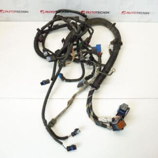
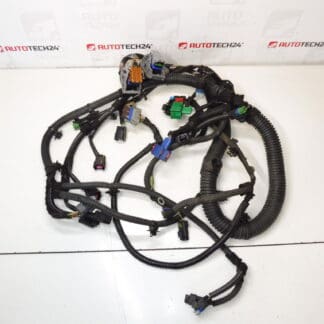
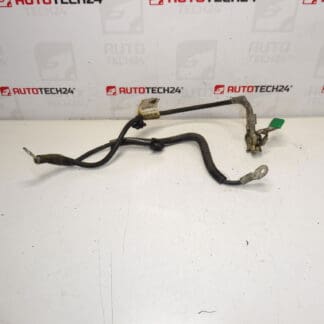
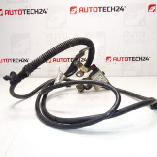
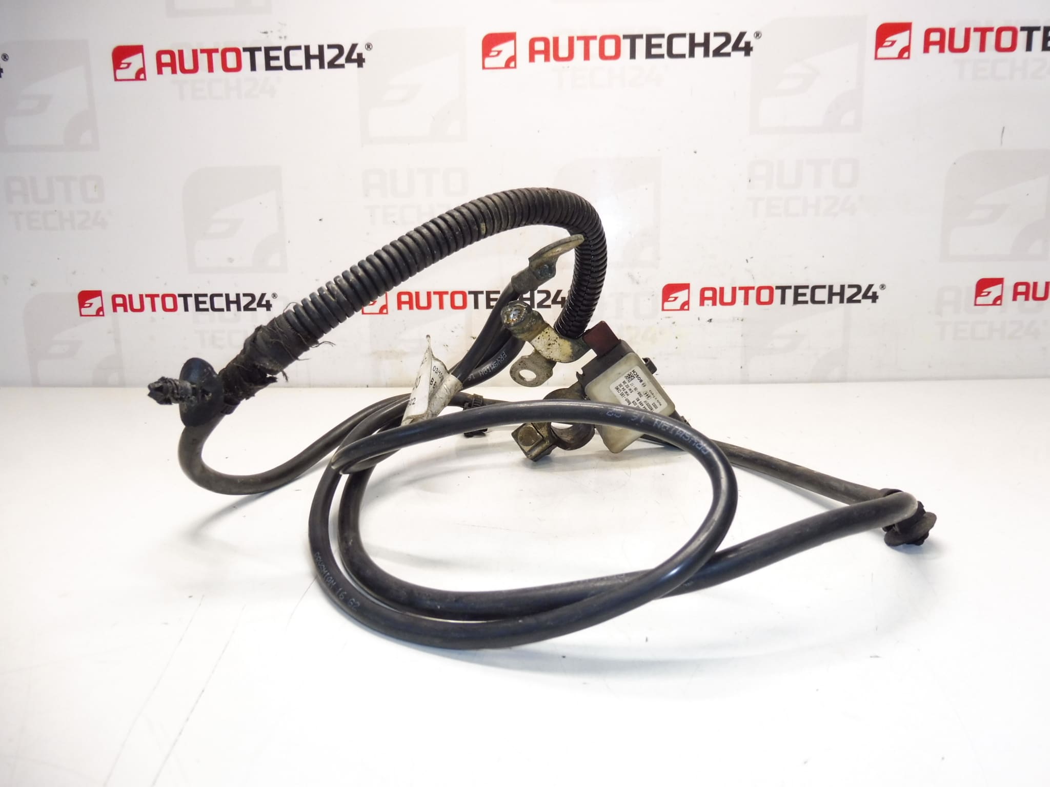
Negative Battery Terminal Cable With Control Unit For Citroën And Peugeot Vehicles.
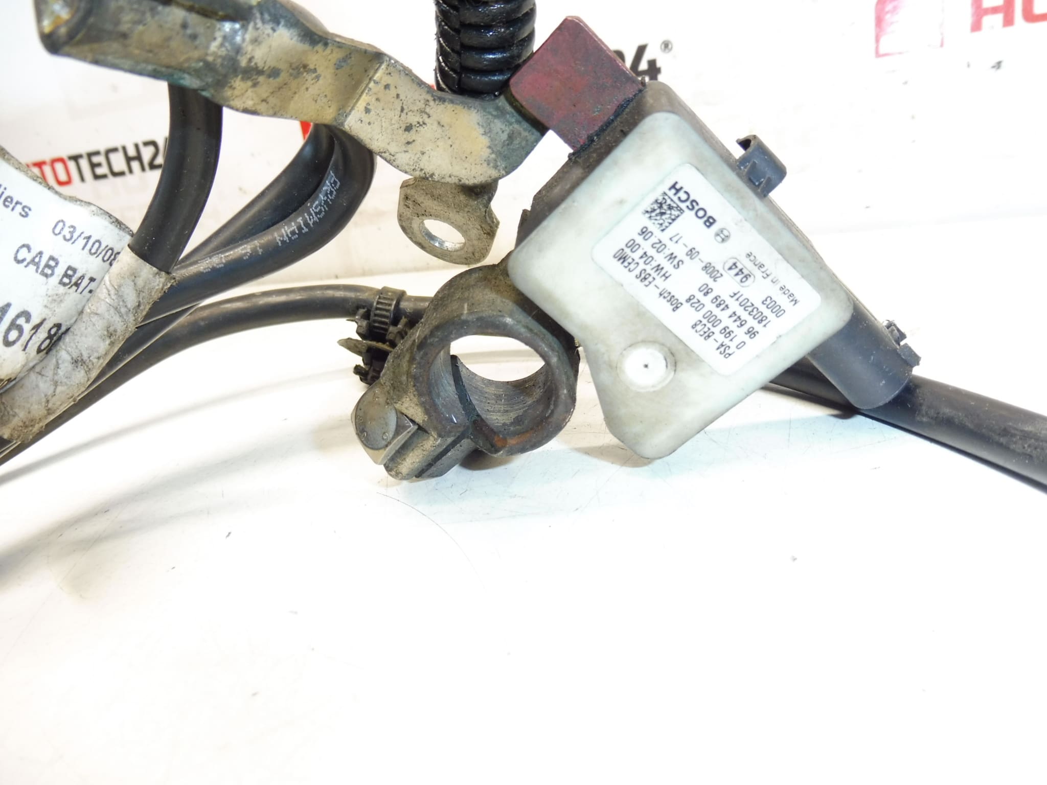
This negative battery terminal cable with integrated control unit is a direct-fit replacement commonly used on Citroën and Peugeot models. Supplied under OEM references 9664448980 and 9663716180 (also referenced as 5638VZ / NFP), the assembly combines the main ground conductor with a small control/sensor module that interfaces with the vehicle electrical system. Ideal for professional workshops and experienced DIY mechanics, this part restores reliable grounding, battery condition monitoring and charging management—critical on vehicles with advanced battery management or start‑stop systems.
Features and Benefits: improved electrical contact at the negative post, preserved communication between the battery sensor and vehicle control units, simple plug‑and‑play replacement where original connectors are used, and quick diagnostics when searching by product code. Frequently searched by part number, the cable helps eliminate intermittent faults, charging errors and start/stop irregularities that result from a failing ground or sensor unit.
Technical Information
- Manufacturer: Stellantis (Citroën / Peugeot)
- Model: Citroën C5 X7; Peugeot 407 (commonly fitted to 1.8 16V and 2.0 16V variants)
- Product Codes: 9664448980, 9663716180
- Additional Numbers: 5638VZ, NFP
Installation Recommendations
Work Should Be Performed By A Qualified Technician Or A Competent DIY Mechanic Familiar With Vehicle Electrical Systems. Before Starting, Isolate The Vehicle’s Electrical System Following Standard Safety Practices (Remove Ignition Key, Wear Protective Gloves And Eye Protection). Disconnect The Negative Terminal (And Then The Positive If Needed) To Avoid Short Circuits. Remove The Old Cable: Unplug Any Sensor/Control Connectors, Undo Fasteners And Remove The Clamp From The Battery Negative Post And Chassis Ground. Fit The New Cable In Reverse Order, Ensuring All Connectors Seat Firmly And Wiring Is Routed Away From Heat Sources And Moving Parts. Tighten Battery Connections To Manufacturer’s Specified Torque And Reconnect Battery Last. After Installation, Check For Fault Codes And Verify Charging And Start‑Stop Functions Operate Normally.
Most Common Failure Causes
Failures Typically Result From Corrosion At The Battery Post Or Ground Points, Mechanical Fatigue From Engine Bay Vibration, Water Ingress Or Damage To The Small Control Module/Sensor, And Overheating Or Loose Connections Leading To High Resistance. Symptoms Include Difficult Starting, Battery Warning Or Charging Fault Messages, Reduced Alternator Performance, Intermittent Electrical Faults And Erratic Start‑Stop Operation.
When ordering, use the OEM part numbers listed above to ensure you receive the correct cable assembly for vehicles that require an integrated control module. This replacement restores proper grounding and battery monitoring to help maintain reliable engine starts and stable vehicle electrics.