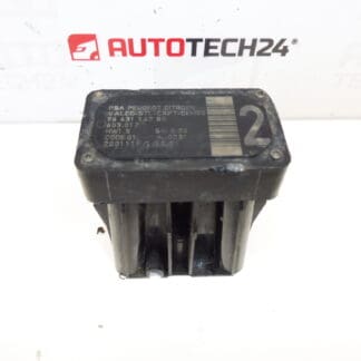
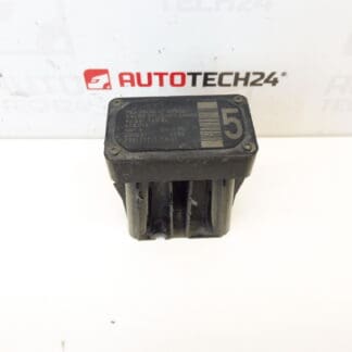
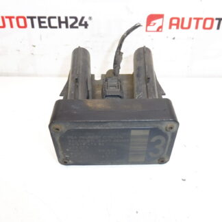
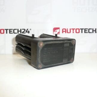
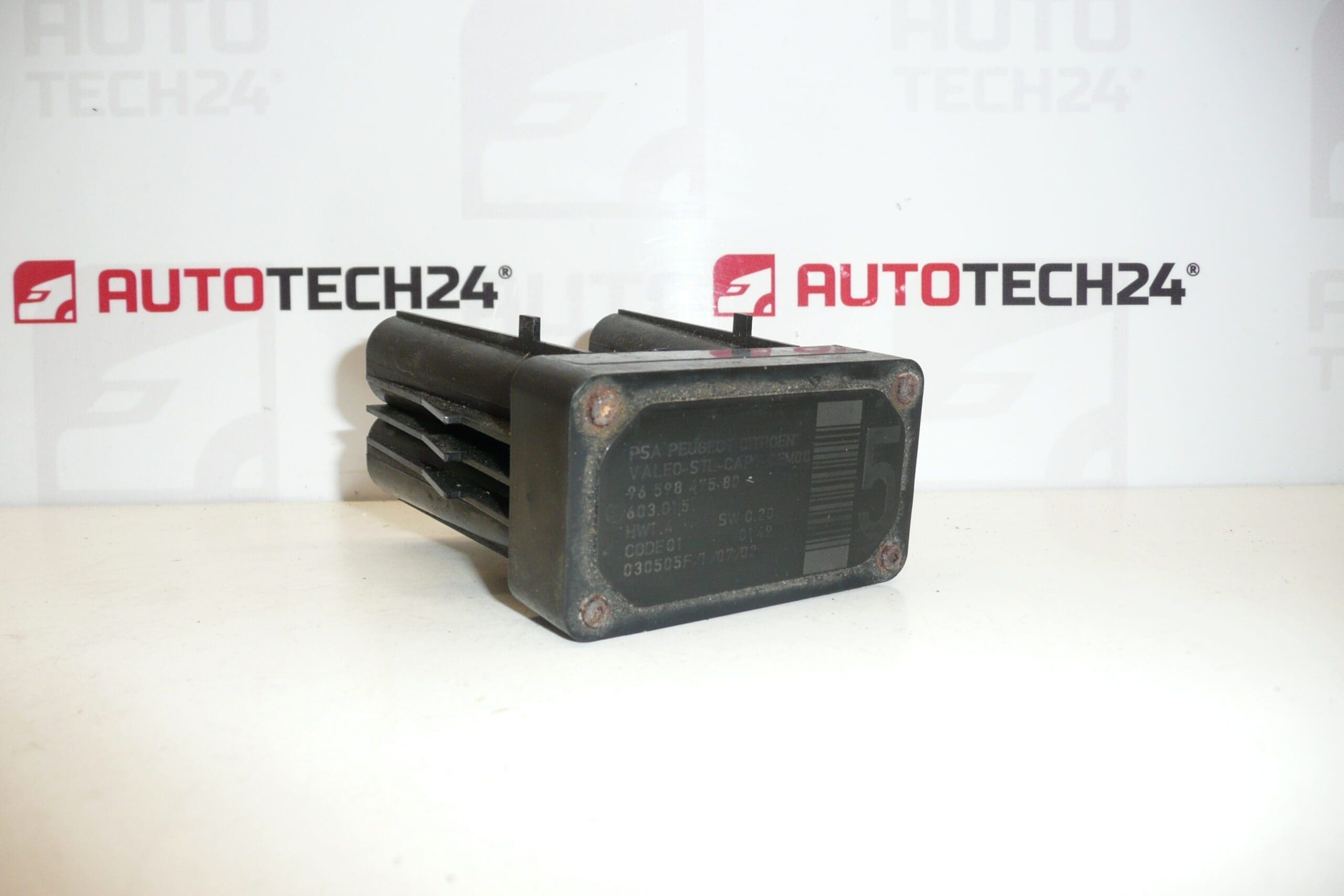
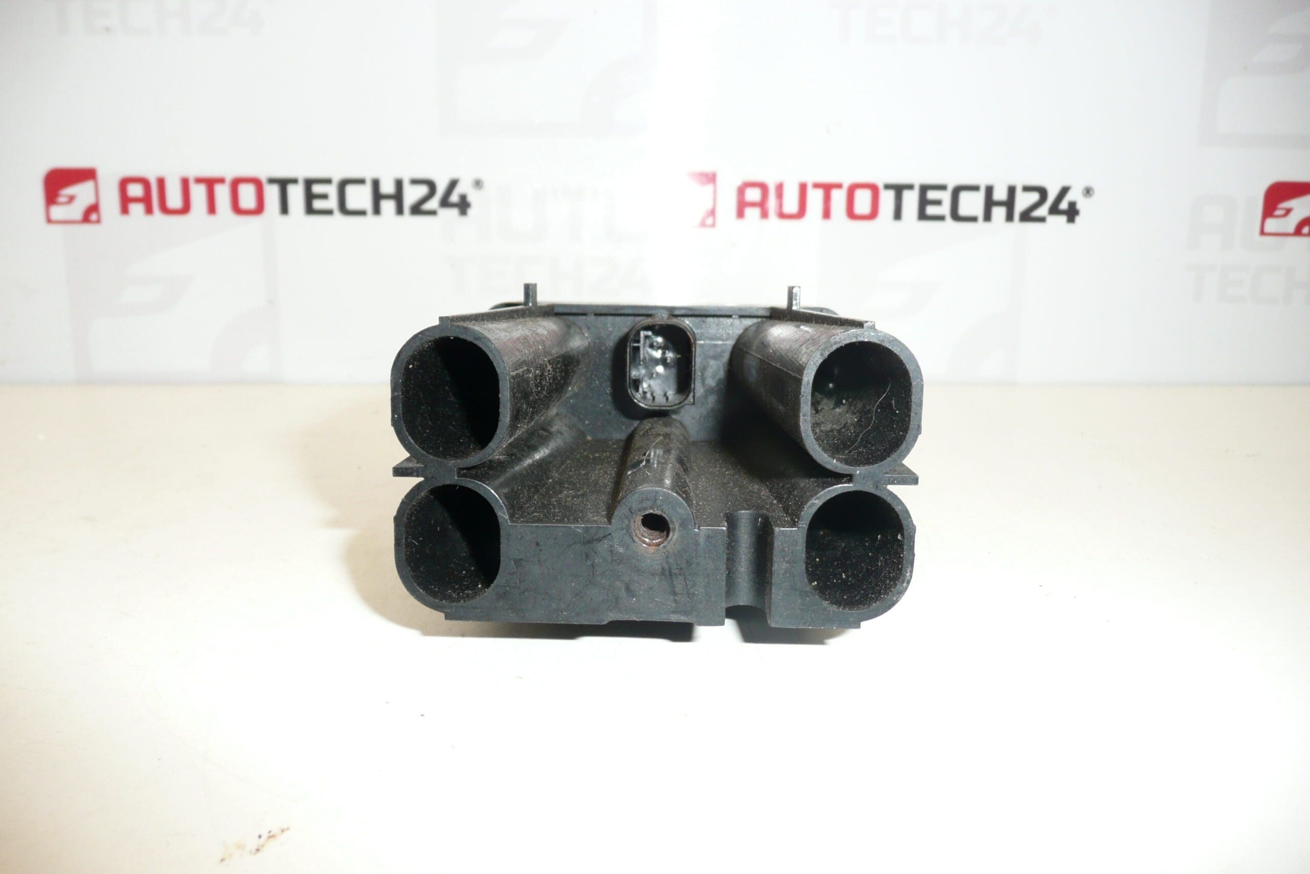
AFIL sensor 5 Citroën Peugeot 9659847580 6590W1

61.00

Stellantis CITROEN PEUGEOT
9659847580 603.015 6590W1

1 in stock

SKU: 2091-I7_K14 M2091 Categories: , , Tags: ,

Description

Lane driving sensor AFIL number 5 for CITROEN PEUGEOT
cars
There may be a broken screw that holds the unit to the undercarriage – must be unscrewed

Part description

This AFIL sensor (Lane Driving Sensor) is intended for Citroën/Peugeot cars and is mainly searched by part number 9659847580 or code 6590W1. It is an electrical component that cooperates with the lane-keeping assistance system and is important for the correct function of the notification/warning in case of unintentional lane departure.

Practical disassembly note: it may happen that the screw holding the unit to the undercarriage is notched – in this case it needs to be drilled out.

Technical information

  • Manufacturer: Stellantis
  • Model: Citroën C4; Citroën C4 PICASSO; Citroën C5; Citroen C5 X7; Citroën C6; Peugeot 308; Peugeot 407
  • Other numbers: 603.015

Product codes

  • Product codes: 9659847580, 6590W1, 603.015

Installation recommendations

Generally/typically for this type of electro sensor, the exact location and procedure may vary depending on the specific model and design of the car. Follow the service procedure for the vehicle in question.

1) Before assembly

  • Compare old and new part: same numbers (9659847580 / 6590W1), shape, brackets and connector.
  • Check the connector and pins (oxidation, bending, pulled pins), the condition of the wiring in the vicinity and the cleanliness of the contact surfaces.
  • Check whether the sensor packaging is not damaged (cracks, deformation) and whether the handles are not broken.

2) Necessary tools and materials

  • Basic set of hand tools (ratchet/extension, screwdrivers, or torx according to design).
  • A pry bar/clip pliers for plastic clips will usually help to work in the undercarriage.
  • In the case of a damaged screw: tools for drilling (drill, screw extractor depending on the situation) and tools for loosening the threads.
  • Electrical contact cleaner (as needed) and protective gloves.

3) Step-by-step assembly procedure

  1. Turn off the ignition, wait a while for the system to sleep and disconnect the battery (typical practice for electrical parts).
  2. Secure the vehicle against movement and prepare access to the mounting location according to the vehicle design.
  3. Remove the necessary covers/protective parts (typically plastic parts and clips) to access the sensor.
  4. Disconnect the electrical connector: first release the connector lock, then carefully pull the connector without prying the cables.
  5. Unfasten the sensor. If the screw is notched, proceed with caution and prepare to drill out so as not to damage the surrounding parts and the thread.
  6. Remove the old sensor and check the seating area (dirt, corrosion, deformation of the holder).
  7. Install the new/used sensor into the holder in its original position so that it fits properly and is not under tension.
  8. Tighten the fasteners adequately and evenly (no over-tightening – this is an electrical part with a holder).
  9. Connect the connector as far as it will go and check the safety of the connector fuse.
  10. Reinstall any covers and clips that were removed and check that nothing rubs against the wiring.
  11. Connect the battery and perform a basic check of the electrical installation (no error messages, no contact interruption).
    • 4) Post-assembly checks and test drive/function verification

      • Check that there are no warning messages related to the driving assistance system when the ignition is switched on.
      • If you have diagnostics, check the stored faults and delete them if necessary (according to normal practice after replacing an electrical part).
      • Do a careful test drive and observe the behavior of the lane departure warning system (if it is active in the car’s equipment).

      5) The most common assembly mistakes + how to avoid them

      • Exchanging a part (different number/code) → always compare the codes 9659847580 / 6590W1 and the design of the connector.
      • Damage to connector/pins during disassembly → release fuses, do not pull on cables, use contact cleaner.
      • Torn/torn fastening → tighten with feeling; when the screw is engaged, drill in a controlled manner and protect the surroundings.
      • Poor seating in the holder → check the seating surfaces and the cabling to ensure that it is not under tension.

      Reasons why the part is damaged

      • Mechanical damage (impact, contact with an obstacle, damage in the undercarriage area).
      • Corrosion and humidity at the installation site, oxidation of connectors and transition resistances.
      • Damage to the cabling (abrasion, pinching, pulling on the bundle, poorly guided attachment).
      • Unprofessional disassembly/assembly – torn threads, snapped screws, cracked holders, damaged pins.
      • Vibration and prolonged stress on the mounts leading to loosening or cracking.

Additional information

Weight 0.3 kg