Description
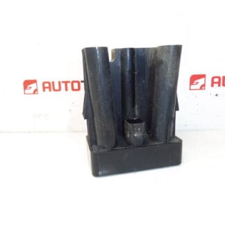
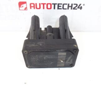
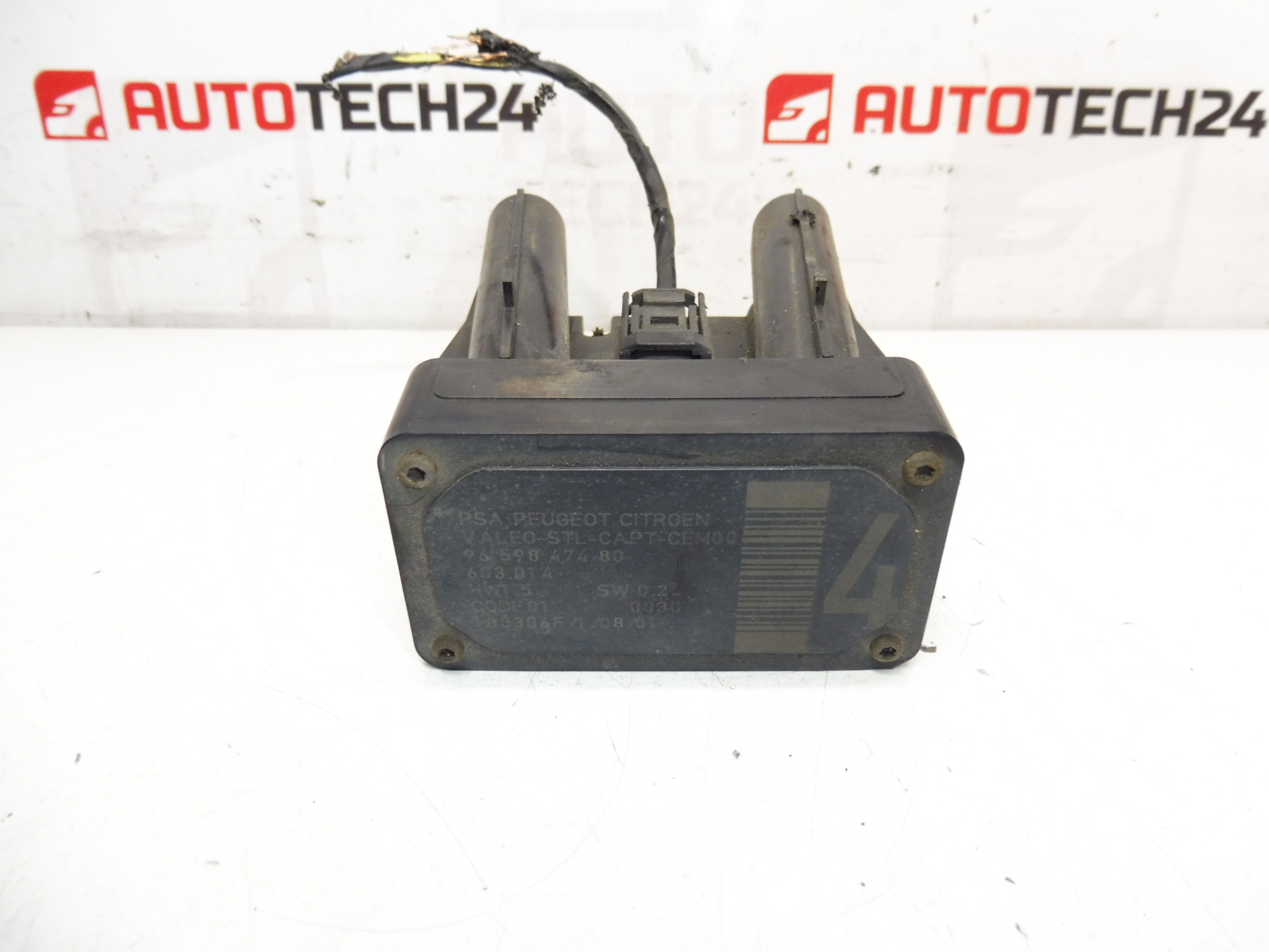
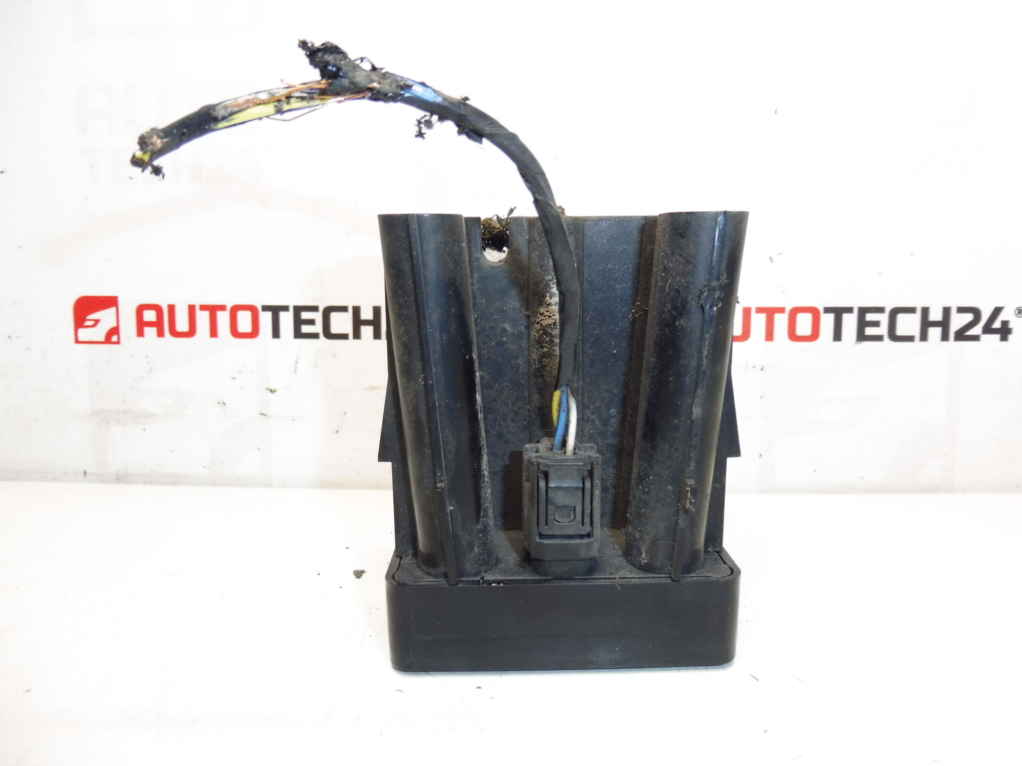
AFIL Lane Departure Monitoring Sensor Number 4 for Citroën and Peugeot Vehicles. The screw that holds the unit to the wheel arch may be seized — drilling out may be necessary.
This AFIL (Lane Departure) sensor is an OEM-type electronic component used on a range of Citroën and Peugeot models to monitor lane-keeping functions and support the driver assistance system. Designed for professional fitment by mechanics and experienced DIYers, the unit matches common Stellantis part references and is often searched for by its product codes (9659847480, 6590W1). The compact sensor mounts to the vehicle body and communicates with the vehicle’s safety electronics to detect lane departure conditions and trigger warnings or interventions.
Technical Information
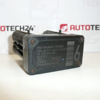
- Manufacturer: Stellantis (Citroën / Peugeot)
- Model: AFIL Sensor Number 4
- Product Codes: 9659847480, 6590W1
- Additional Numbers: 603.014
- Compatible Vehicles: Citroën C4, Citroën C4 Picasso, Citroën C5 (including C5 X7), Citroën C6, Peugeot 308, Peugeot 407
Installation Recommendations
Before starting work, park the vehicle on a level surface and isolate the battery to avoid accidental short circuits. Typical replacement steps:
- Remove the relevant wheel arch liner or inner trim to access the sensor mounting point.
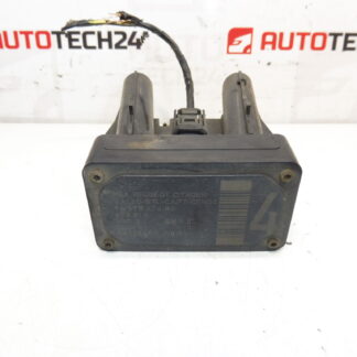
- Disconnect the electrical connector and inspect pins for corrosion or damage.
- If the mounting screw is seized to the wheel arch, carefully drill or extract the screw; use penetrating oil and the correct drill/extractor tools to avoid damaging the housing or bodywork.
- Fit the new sensor, use new fasteners if the original is damaged, and secure with appropriate torque and anti-seize where advisable.
- Reconnect the electrical connector and reassemble trim. Clear any stored fault codes with an OBD scanner and perform a system check. A software reset or calibration may be required depending on the vehicle’s driver assistance system.
Why The Part Most Often Fails
- Corrosion And Water Ingress: Exposure to road salt and moisture can corrode connectors and internal electronics.
- Impact Damage: Bumper or wheel-arch impacts from minor collisions or curb strikes can physically damage the sensor or its mounting.
- Seized Fasteners: The mounting screw can seize to the body panel over time, making removal difficult and sometimes damaging the housing during extraction.
- Wiring And Connector Issues: Broken wires, crushed insulation, or poor electrical contact cause intermittent faults or complete failure.
Fitment And Replacement Notes
This sensor is not typically a scheduled wear item; failures are usually related to external damage or environmental exposure. When replacing, inspect surrounding wiring, harness routing, and connectors. Keep a record of fault codes before replacement and verify the lane-assist function after installation. If the original mounting screw is seized, plan to replace the fastener and treat the new threads to prevent future seizure.
Suitable For Mechanics And Skilled DIYers: The part is intended for technicians comfortable with body-trim removal, electrical connectors and basic diagnostics. Having an OBD scanner or diagnostic tool will speed up fault clearing and verification after installation.