Description
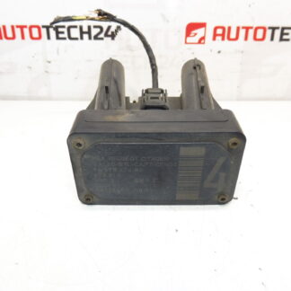
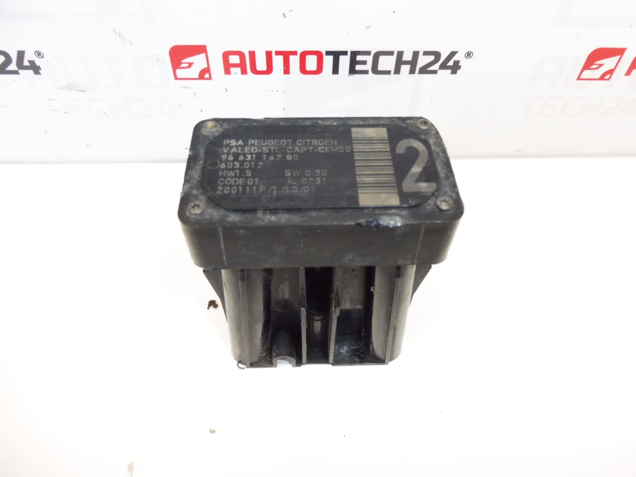
AFIL lane-keeping sensor number 4 for Citroën and Peugeot vehicles. The screw that secures the unit to the wheel arch may be seized – drilling out may be necessary.
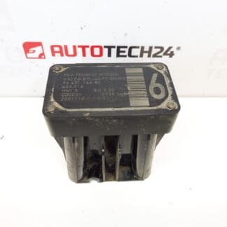
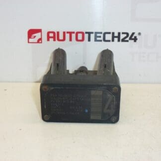
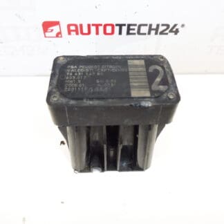
This AFIL (Lane Departure/Lane Keeping) sensor is a direct-fit safety component used on a range of Citroën and Peugeot models. Ideal for professional workshops and experienced DIY mechanics, the unit restores proper lane-monitoring function and eliminates error codes related to AFIL channel 4. Common search terms and part numbers associated with this item (9663116280, 6590W1) make it easy to find in parts catalogs and diagnostic listings.
Technical Information
- Manufacturer: Stellantis (Citroën / Peugeot)
- Model: Citroën C4, Citroën C4 Picasso, Citroën C5, Citroën C5 X7, Citroën C6, Peugeot 308, Peugeot 407
- Product Codes: 9663116280, 6590W1
- Other Numbers: 603.012
Compatibility is based on the listed part numbers and model families. Always confirm the part number stamped on the old sensor before ordering to ensure identical fit and connector type.
Function
The AFIL sensor monitors lane position and supplies data to the vehicle’s lane departure/assist system. When functioning correctly it helps detect unintentional lane drift and supports driver-warning or corrective systems. Faulty AFIL sensors typically trigger fault codes and can disable lane-assist features.
Installation Recommendations
Recommended for installation by trained mechanics or competent DIYers with basic electrical and bodywork skills. Typical replacement steps:
- Disconnect the vehicle battery before starting to avoid short circuits.
- Remove inner wheelarch liner or relevant trim to access the sensor mounting.
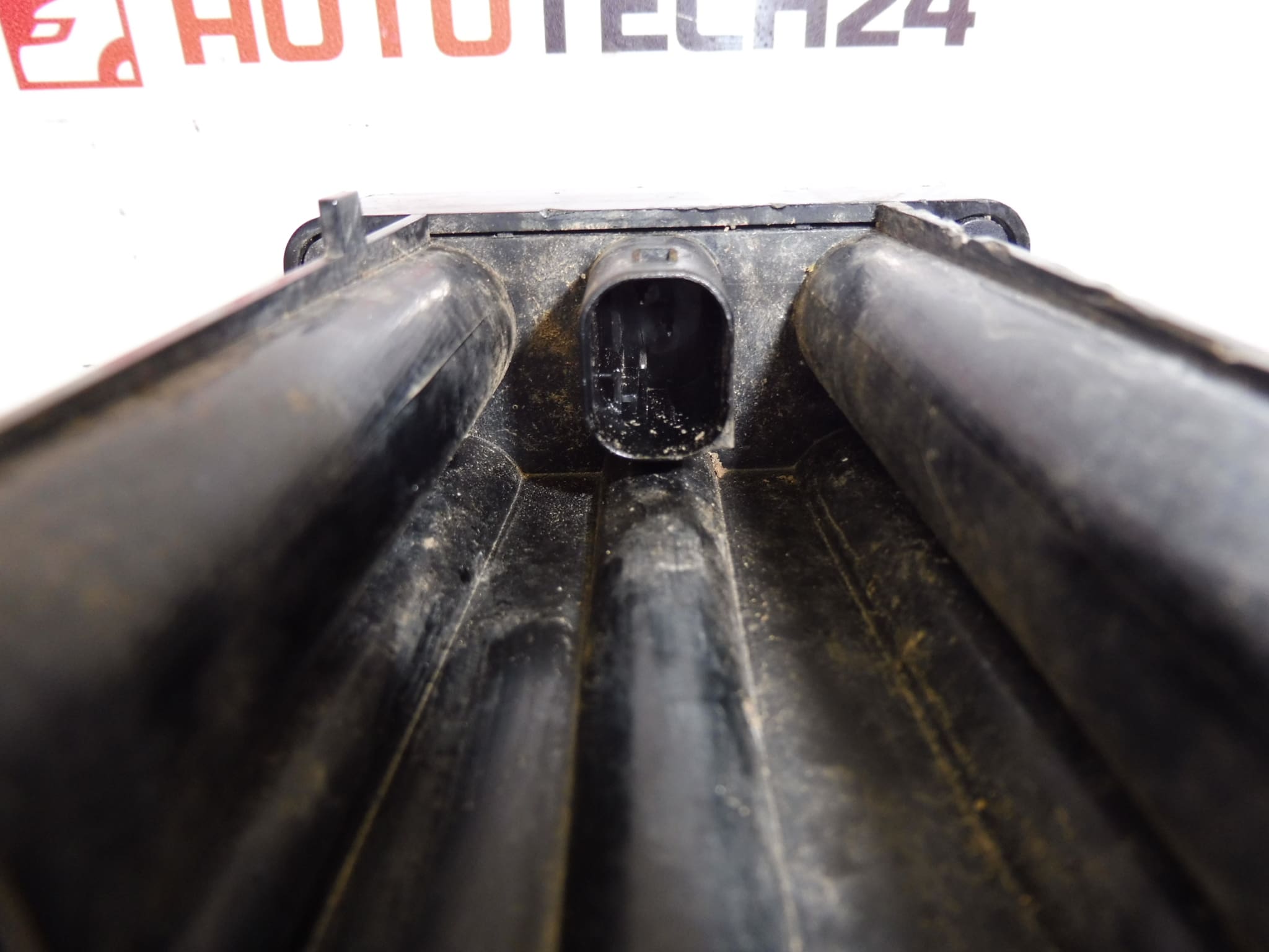
- Unplug the sensor electrical connector and remove mounting fasteners. Note: The mounting screw may be seized or corroded—drilling out the screw or carefully extracting it may be required (as noted in the original technical comment).
- Fit the new sensor, secure with appropriate hardware, reconnect the plug, and reassemble trim.
- Perform a diagnostic scan and, if required, calibrate or initialise the lane-assist system with a suitable diagnostic tool to clear codes and confirm correct operation.
Why This Part Fails Most Often
Typical failure causes include corrosion and water ingress at connectors, mechanical damage from impacts, wiring or connector deterioration, and seized mounting screws due to rust. Environmental exposure and road debris accelerate wear. There is no fixed replacement interval—replace the sensor when fault codes appear or when lane-assist warnings are present.
Replacing a faulty AFIL sensor restores lane-monitoring performance, prevents warning lights and error codes, and ensures that the vehicle’s safety assists operate as designed. Keep the part numbers handy (9663116280 / 6590W1) to speed up ordering and verification in parts lists.