Description
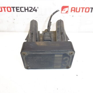
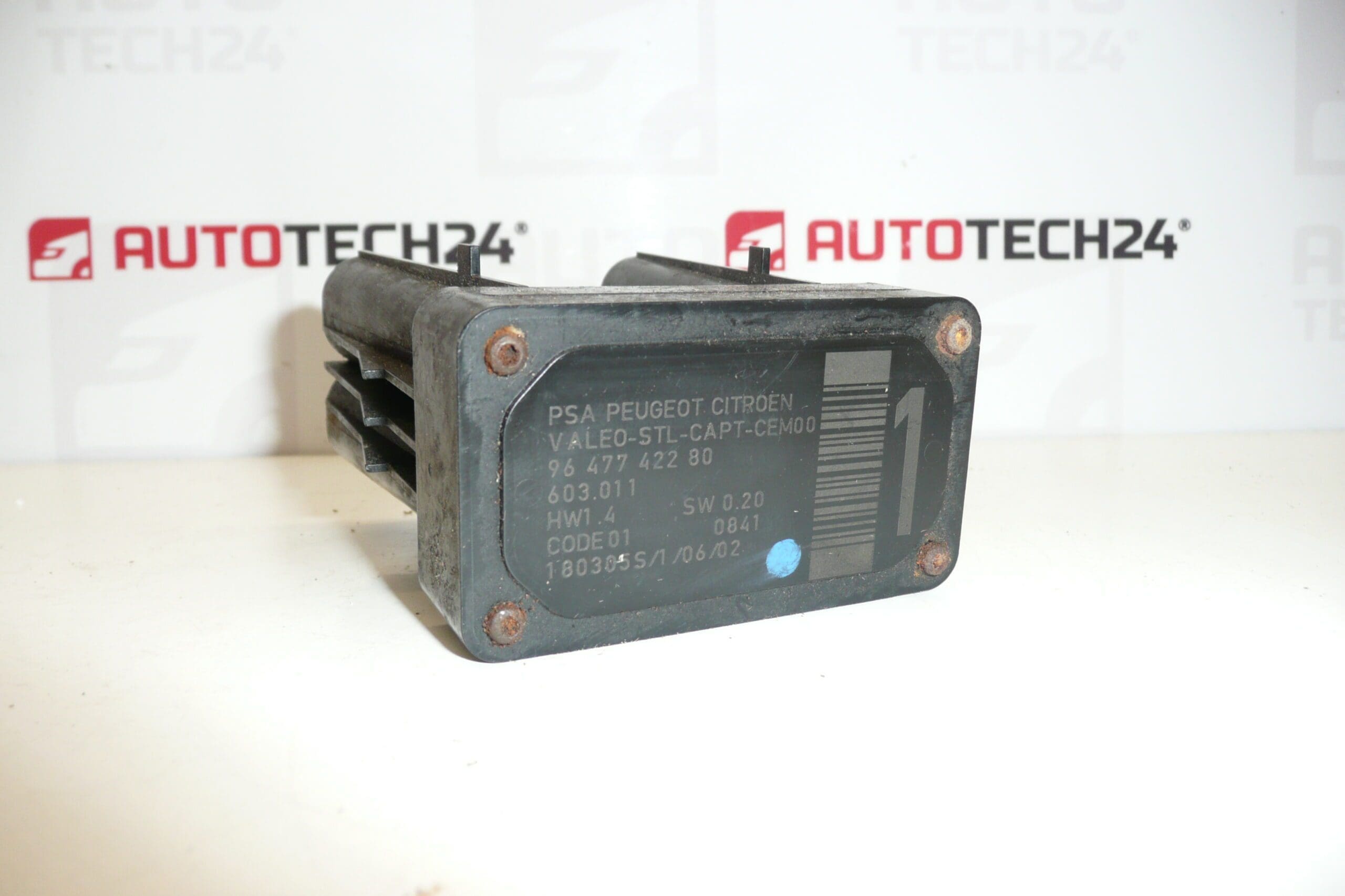
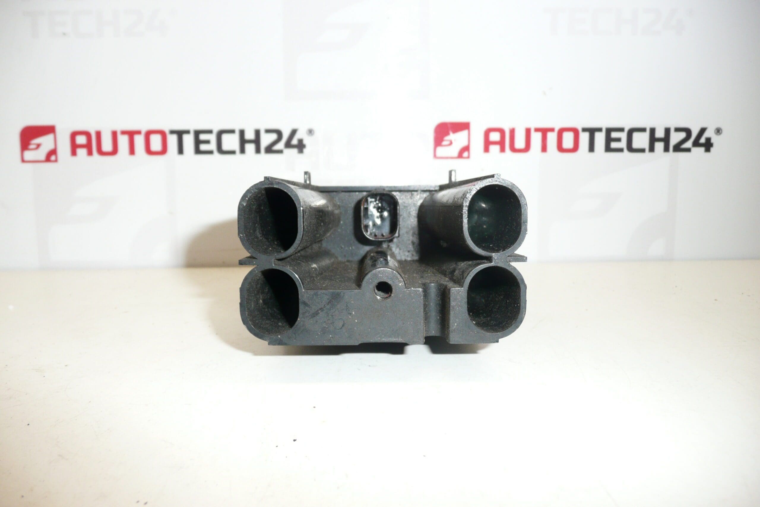
AFIL lane departure monitoring sensor number 1 for Citroën and Peugeot vehicles. A screw that secures the unit to the wheel arch may be seized and could need to be drilled out.
This AFIL (Lane Departure Monitoring) sensor is a direct replacement part commonly referenced by OE numbers 9647742280 and 6590W1. It is designed for workshops and DIY mechanics who service Citroën and Peugeot vehicles and need a reliable, searchable reference by product code. Use keywords such as AFIL sensor, lane keeping sensor, 9647742280, and 6590W1 when locating the part for quick match with vehicle compatibility lists.
The sensor’s role is to monitor the vehicle’s position relative to lane markings and supply information to lane-keeping and lane-departure warning systems. A correctly functioning AFIL sensor is essential for the proper operation of driver assistance features that help prevent unintentional lane departure.
Technical Information
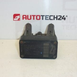
- Manufacturer: Stellantis / Citroën / Peugeot
- Model: Citroën C4; Citroën C4 Picasso; Citroën C5; Citroën C5 X7; Citroën C6; Peugeot 308; Peugeot 407
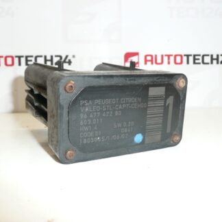
- Product Codes: 9647742280; 603.011; 6590W1
- Additional Numbers: 6590W1; 9647742280
Replacement And Installation Notes
Typical replacement steps for a qualified mechanic or experienced DIYer:
- Disconnect the negative battery terminal before starting electrical work.
- Access the sensor—it is commonly mounted near the wheel arch or inner fender; remove the wheel and inner wheel arch liner if required to reach the unit.
- Unplug the electrical connector and remove the securing screw(s). Note: The mounting screw can be seized or corroded; penetrating oil and careful extraction are often needed. In some cases the screw must be drilled out as noted above.
- Fit the replacement sensor, secure mounting hardware, reconnect the plug, and replace any removed trim or liners.
- After installation perform system initialization or calibration with an appropriate diagnostic tool according to manufacturer procedure to ensure correct lane-detection alignment.
Installation Recommendations
- Use penetrating lubricant on corroded screws and allow time to soak in before attempting removal.
- Protect plastic trim and wiring when using power tools for screw extraction or drilling.
- Inspect the connector for corrosion or bent pins; clean and apply dielectric grease to protect against moisture.
- Replace any damaged clips or fasteners to avoid vibration or misalignment after fitment.
- Carry out a diagnostic check and calibration after installation to confirm system operation.
Why This Part Fails
Common causes of AFIL sensor failure include moisture ingress and corrosion, physical impact from minor collisions or road debris, connector and wiring damage, and long-term degradation from road salt and harsh environments. In many cases the mounting screw corrodes or seizes to the bodywork, which complicates removal and leads to the note about potentially needing to drill out the fastener.
Practical Tips For Mechanics
- Search by OE numbers 9647742280 or 6590W1 to quickly find compatible replacements.
- When replacing the sensor, verify wiring integrity and secure mounting to avoid false warnings or degraded performance.
- Keep a small selection of replacement fasteners and clips on hand—these are frequently damaged during access.
Suitable For: Citroën C4, Citroën C4 Picasso, Citroën C5, Citroën C5 X7, Citroën C6, Peugeot 308, Peugeot 407. Use the provided product codes to confirm fitment in parts catalogs and service manuals.