Description
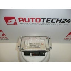
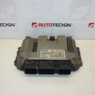
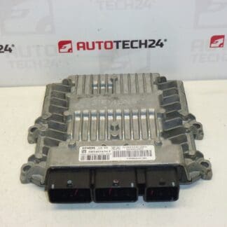
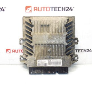
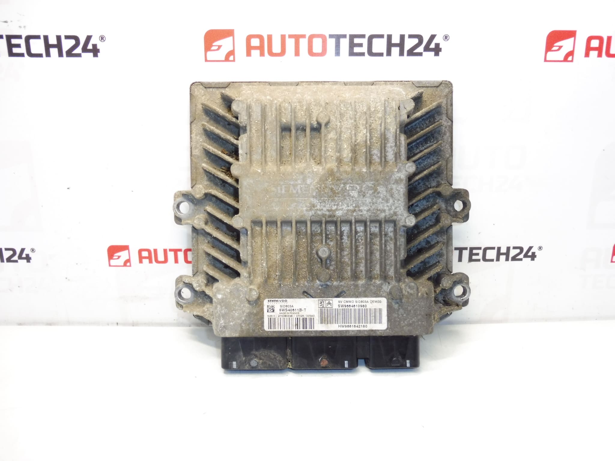
Injection Control Unit Continental Siemens SID803A. It is from a 2007 Citroën C8 2.0 HDi RHK.
Overview
This injection control unit (ECU) Siemens SID803A is a genuine used engine management module for PSA 2.0 HDi diesel engines. It Controls Fuel Injection Timing, Injector Drivers And Basic Engine Management Functions And Is Identified By Common Product Codes To Help You Find Exact Replacements (SID803A, 5WS40611B-T, 9661642180, 9664610980, 1942JF). Suitable For Vehicles That Use The Same Siemens/Continental SID803A Hardware, Most Notably Citroën C8 2.0 HDi (RHK) And Vehicles With Matching Part Numbers Such As Peugeot 807.
Technical Information
- Manufacturer: Continental / Siemens VDO
- Model: Siemens SID803A (Injection Control Unit)
- Product Codes: 5WS40611B-T, 5WS40611B-T (alternative writing), SID803A
- Other Numbers: 9661642180, 9664610980, 1942JF
Key Features And Function
The ECU Manages Diesel Injection Control (Injector Timing And Duration), Engine Sensors, And Interfaces With Other Vehicle Systems To Ensure Proper Combustion, Emissions Control And Engine Performance. Faulty Or Damaged Modules Can Cause No Start, Limp Mode, Rough Idle, Misfires, Reduced Power And Increased Fuel Consumption.
Replacement And Installation Guide
Basic Replacement Steps (General Guidance For Experienced Mechanics Or DIY Enthusiasts):
- Disconnect The Battery Before Any Work To Prevent Damage To The Unit And Electrical System.
- Access The ECU Location (Varies By Vehicle; Often Mounted In Engine Bay Or Under Dash). Remove Any Trim Or Protective Covers.
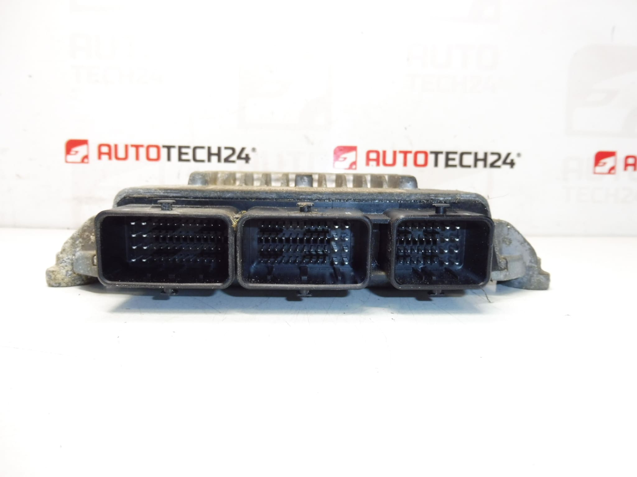
- Carefully Unplug Electrical Connectors And Release Mounting Fasteners. Note Connector Positions And Any Bracket Orientation For Reassembly.
- Install The Replacement Unit, Refit Mounts And Reconnect All Electrical Plugs Securely. Ensure Connectors Are Clean And Dry; Use Contact Cleaner If Necessary.
- After Mechanical Installation, Follow Commissioning Steps Below For Coding Or Cloning To Restore Full Functionality.
Installation And Coding – Important
– The Unit Is Used And Is “Paired” With The Original Vehicle (VIN/PIN/Keys).
– Options For Commissioning:
1) Cloning Data From The Old Unit (EEPROM/Flash) – After A Successful Clone The Unit Is Plug And Play.
2) Virginization And Subsequent Initialization/Telecoding Via DiagBox (Possibly Online) + Key Adaptation.
– Recommended To Be Performed By A Qualified Technician With PSA Service Equipment (DiagBox/Lexia/PP2000).
– Before Removal/Installation Always Disconnect The Battery And Follow Manufacturer Procedure To Avoid Damaging The Unit.
Why This Part Fails
Common Causes Of Failure Include Moisture Ingress And Connector Corrosion, Thermal Stress And Repeated Heat Cycling, Voltage Spikes Or Poor Electrical Grounds, Contamination From Oil Or Fluids, And Degraded Solder Joints Or Internal Component Wear. Symptoms Often Include Engine Failing To Start, Intermittent Misfires, Limp Mode, Fault Codes Related To Injectors Or Sensor Failures, And Unstable Idle.
Practical Tips
- Check Connectors And Ground Points For Corrosion Before Replacing The ECU; Many Issues Are Connector Related.
- If Possible, Clone The Original ECU Flash/EEPROM To Preserve Vehicle-Specific Adaptations; Otherwise Plan For Coding/Initialization.
- Keep Replacement Unit Dry And Protect It From Direct Heat Sources; Secure Mounting To Avoid Vibration-Induced Damage.
Compatibility Note
This Unit Originates From A 2007 Citroën C8 2.0 HDi (RHK) And Carries The Above Product Numbers. Confirm Physical Match Of Connectors And Part Numbers When Searching For Replacements; Matching The Codes Shown Above Increases The Chance Of Correct Fitment.