Description
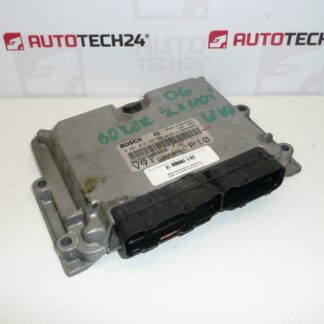
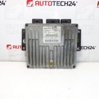
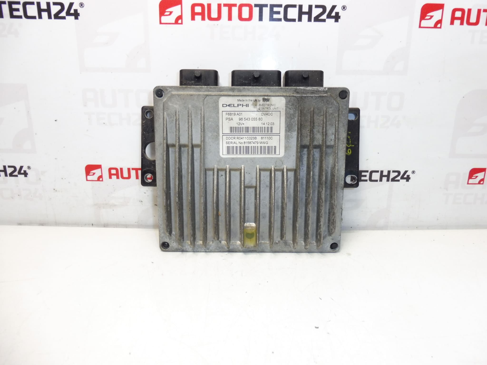
Injection control unit DELPHI 1.4 HDI 66kw
It is from a CITROEN C3
Part description
This ECU (injection control unit) Delphi is for the 1.4 HDI (66 kW) diesel engine. It is a used original part from the Stellantis group (Citroën/Peugeot), searched primarily by production and catalog numbers. If you are troubleshooting an injection control or need to replace a damaged unit, correct code matching is key to trouble-free operation.
Technical information
- Manufacturer: DELPHI
- Model: Citroën C3 (listed in the documents)
- Other numbers: 1940VJ, NFP
Product codes
- Product codes: 9654305580, 1940VH
Labels / models (according to documents): Citroën C3, PEUGEOT 1007
Installation recommendations
With injection control units, in general, replacing the part itself is only part of the job — correct data matching and subsequent commissioning is essential. The exact procedure may vary depending on the specific car version and equipment.
1) Before assembly
- Compare the codes on the unit with the old part (especially 9654305580 and 1940VH) and check the DELPHI manufacturer match.
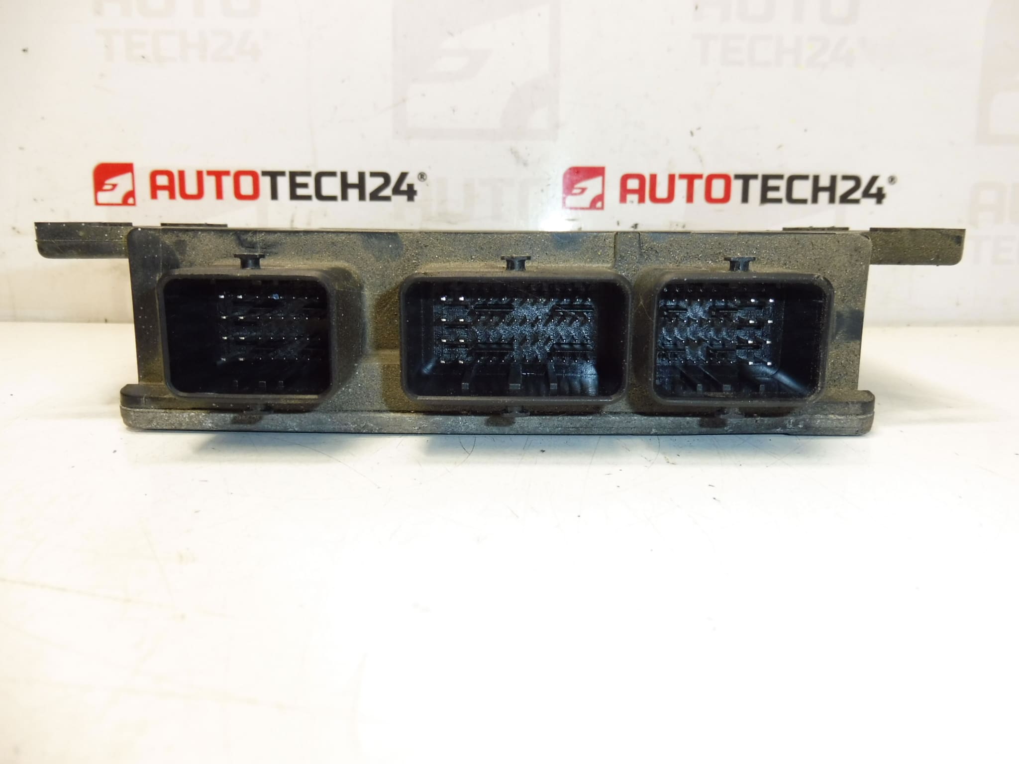
- Visually check the connectors (bent pins, cracks, leaks, damaged connector locking).
- Check the condition of the wiring and grounding in the area (a common cause of repeated problems even after replacing the unit).
2) Necessary tools and materials
- Basic set of hand tools (ratchet/bits, screwdrivers)
- ESD protection (recommended) and clean working environment
- Diagnostics for PSA (for initialization/telecoding as needed)
- Cleaning agent for electrical contacts (according to the condition of the connectors)
3) Step-by-step assembly procedure
- Turn off the ignition and wait for the car to sleep (typically a few minutes).
- Disconnect the battery (follow the manufacturer’s safety procedures).
- Give access to the unit and carefully loosen the fastening (without prying into the body of the ECU).
- Unlock the connectors and disconnect the connectors by pulling on the axis (not by the cables).
- Remove the old unit and compare it with the replacement (codes, connectors, mounts).
- If the connectors are dirty, clean them with a suitable product and let them air out.
- Connect the connectors to the replacement unit and check for proper seating and locking.
- Install the unit back into the bracket/storage and secure it in place.
- Connect the battery.
- Perform the diagnostic steps required for commissioning (see below) and subsequent function check.
-
4) Post-assembly checks and test drive/function verification
- Verify that the car communicates correctly with the ECU via diagnostics and that there are no new faults caused by disconnection.
- Check idle stability and throttle response (if applicable).
- After the test drive, check the connectors and fixings again (vibration can reveal a lack of seating).
5) The most common assembly mistakes + how to avoid them
- Ignoring code matching → always compare unit and manufacturer numbers.
- Connecting/disconnecting live connectors → always disconnect the battery and keep the car asleep.
- Damage to the pins in the connector → disconnect in the axis, do not like, do not pull the cables.
- Missing initialization/coding → take into account that the used ECU may not start up without modification.
Assembly and Coding – Important
– The unit is used and is “paired” with the original car (VIN/PIN/keys).
– Commissioning options:
1) Cloning data from the old drive (EEPROM/Flash) – after the clone, the drive is plug and play.
2) Virginization and subsequent initialization/telecoding via DiagBox (possibly online) + customization of keys.
– Recommended to be performed by a specialist with PSA service equipment (DiagBox/Lexia/PP2000).
– Always disconnect the battery before disassembly/assembly and follow the manufacturer’s procedure to avoid damaging the unit.Reasons why the part is damaged
- Overvoltage in the on-board network (weak battery, bad charging, inappropriate starting, jump connection).
- Moisture and corrosion in the connectors or leakage into the wiring area.
- Damaged cabling, bad grounding or transition resistors in the power supply.
- Incompetent handling (disconnecting the connectors without disconnecting the battery, mechanical stress on the connectors).
- Vibration and thermal stress leading to microcracks of solder joints.