Description
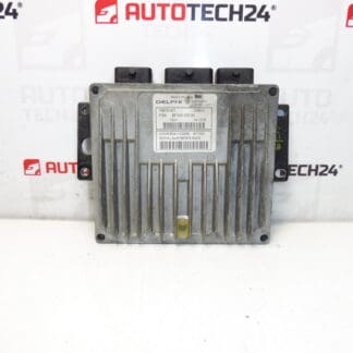
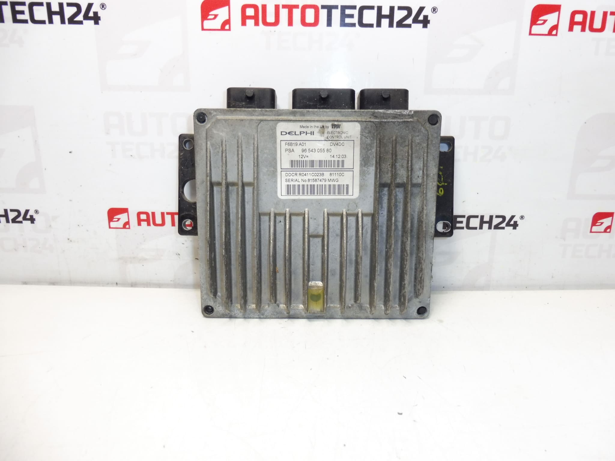
Delphi injection control unit 1.4 HDi 66 kW. It is from a Citroën C3.
This genuine Delphi Engine Control Unit (ECU) is a direct-fit replacement for 1.4 HDi diesel applications used on select Citroën and Peugeot models. Supplied with the well-known part numbers 9654305580, 1940VH and 1940VJ, the module suits workshop professionals and experienced DIY mechanics looking for a reliable engine management control unit. The unit controls fuel injection timing, quantity and injection sequencing to ensure efficient combustion, stable idling and correct operation of emissions-related systems.
Technical Information
- Manufacturer: Delphi
- Model: 1.4 HDi 66 kW
- Product Codes: 9654305580, 1940VH, 1940VJ
- Other Numbers: 1940VJ, NFP (as referenced in supply notes)
Applications
Commonly fitted to: Citroën C3 (1.4 HDi) and compatible Peugeot 1.4 HDi variants such as Peugeot 1007 where the listed part numbers apply. Use the part numbers above when searching or cross-referencing to confirm fitment for specific model years and engine variants.
Symptoms Indicating ECU Fault
When this control unit degrades or fails, typical symptoms include intermittent or permanent engine no-start, stalling, rough or irregular idling, loss of power, sudden limp-home mode activation and persistent engine management warning lamp (MIL). Fault codes related to injection control, communication errors on the CAN bus or sensor/actuator plausibility faults are common diagnostic clues.
Why This Part Fails
ECUs of this type most often fail due to moisture ingress and corrosion of connectors or internal circuitry, thermal stress from prolonged heat exposure, voltage spikes or short circuits in the vehicle electrical system, and physical damage. Poorly secured wiring or water ingress after engine bay cleaning and coolant leaks can accelerate failure.
Replacement And Installation Recommendations
Replacement is straightforward for a trained technician but requires careful procedure:
- Disconnect the negative battery terminal before starting work to prevent electrical damage.
- Locate and remove necessary trim or covers to access the ECU; note the position and orientation of the unit and retain fasteners.
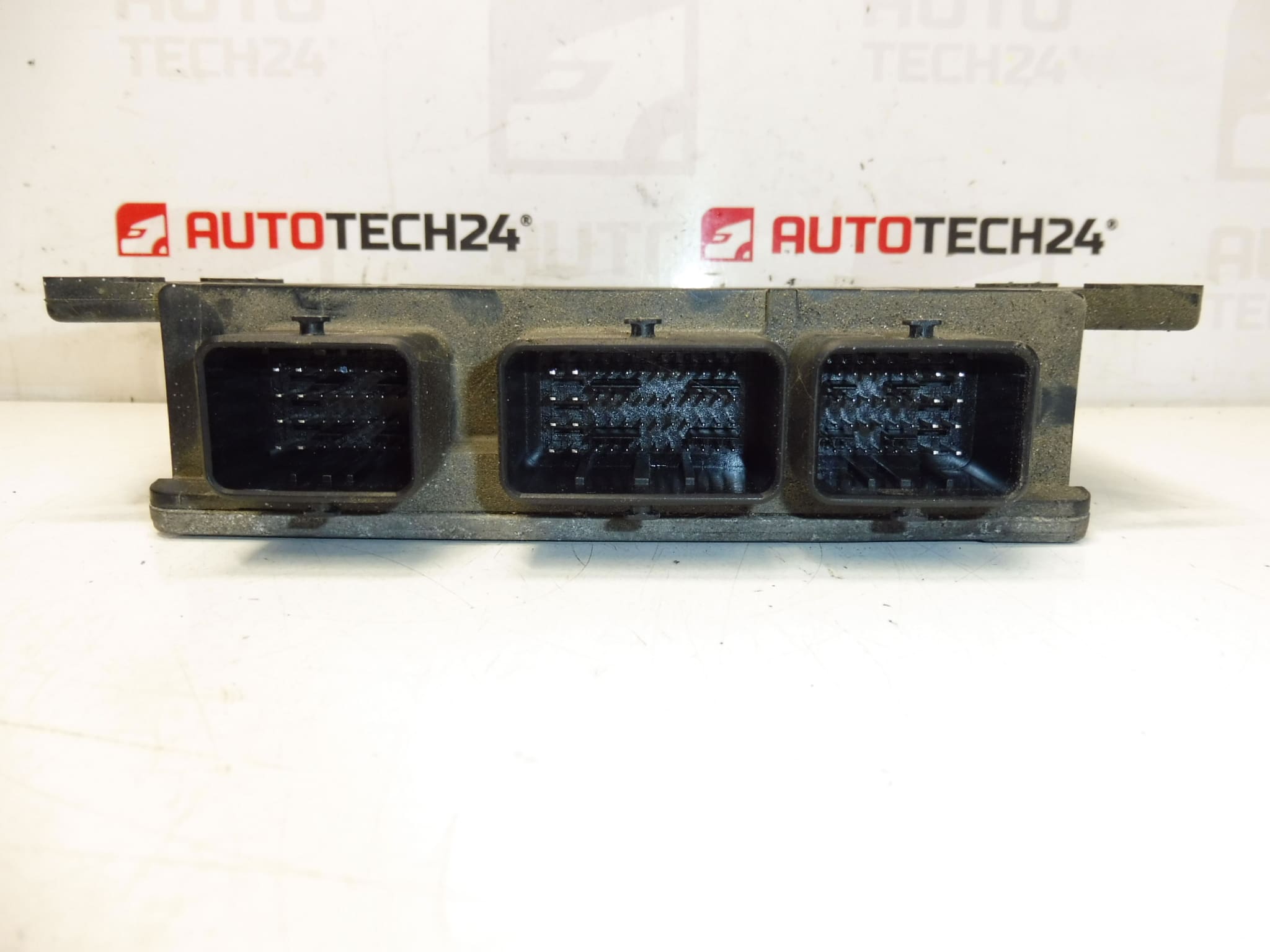
- Carefully unplug all electrical connectors using appropriate release tabs—do not pull on wiring.
- Unbolt the ECU from its bracket and install the replacement in the correct orientation. Reconnect connectors and secure fasteners to the manufacturer’s torque recommendations.
- After mechanical installation, ECU replacement typically requires professional programming/coding to match vehicle immobiliser and engine parameters. Use suitable diagnostic equipment to perform adaptation and to clear/verify fault codes.
Maintenance Tips
Protect connectors with dielectric grease after fitting where appropriate, ensure wiring looms are routed away from heat sources and moving parts, and keep the engine bay free from persistent moisture to prolong ECU life. Regularly inspect connectors for corrosion or looseness during scheduled maintenance.
Part numbers and model references are provided to facilitate fast identification in search engines and parts catalogs—entering codes such as 9654305580, 1940VH or 1940VJ in your parts search will help locate the correct ECU for 1.4 HDi applications.