Description
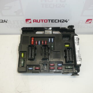
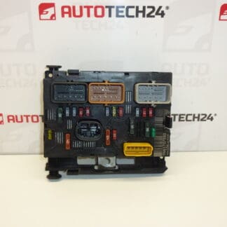
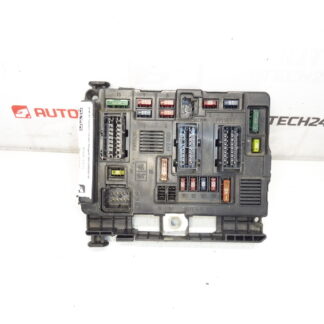
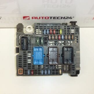
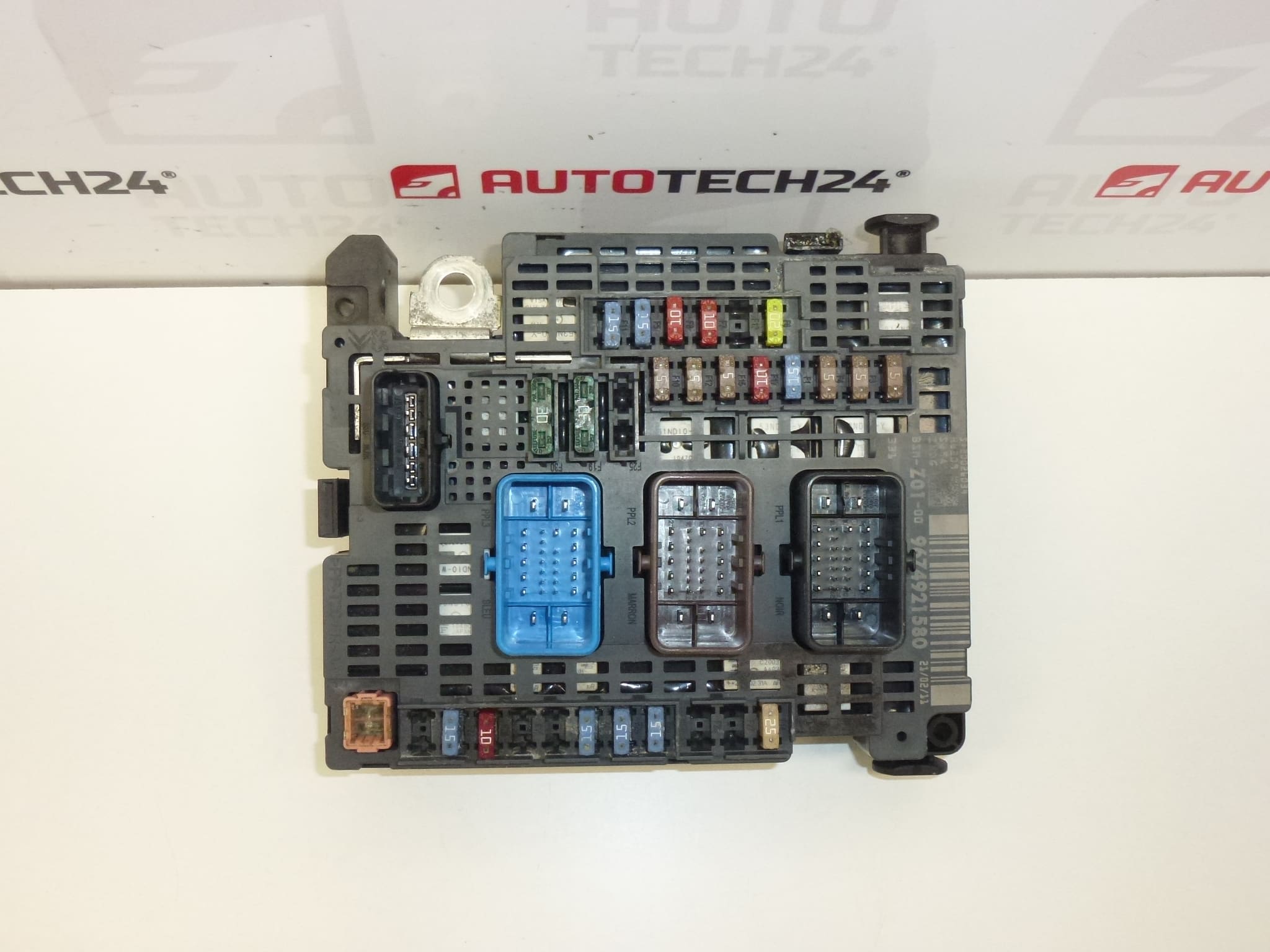
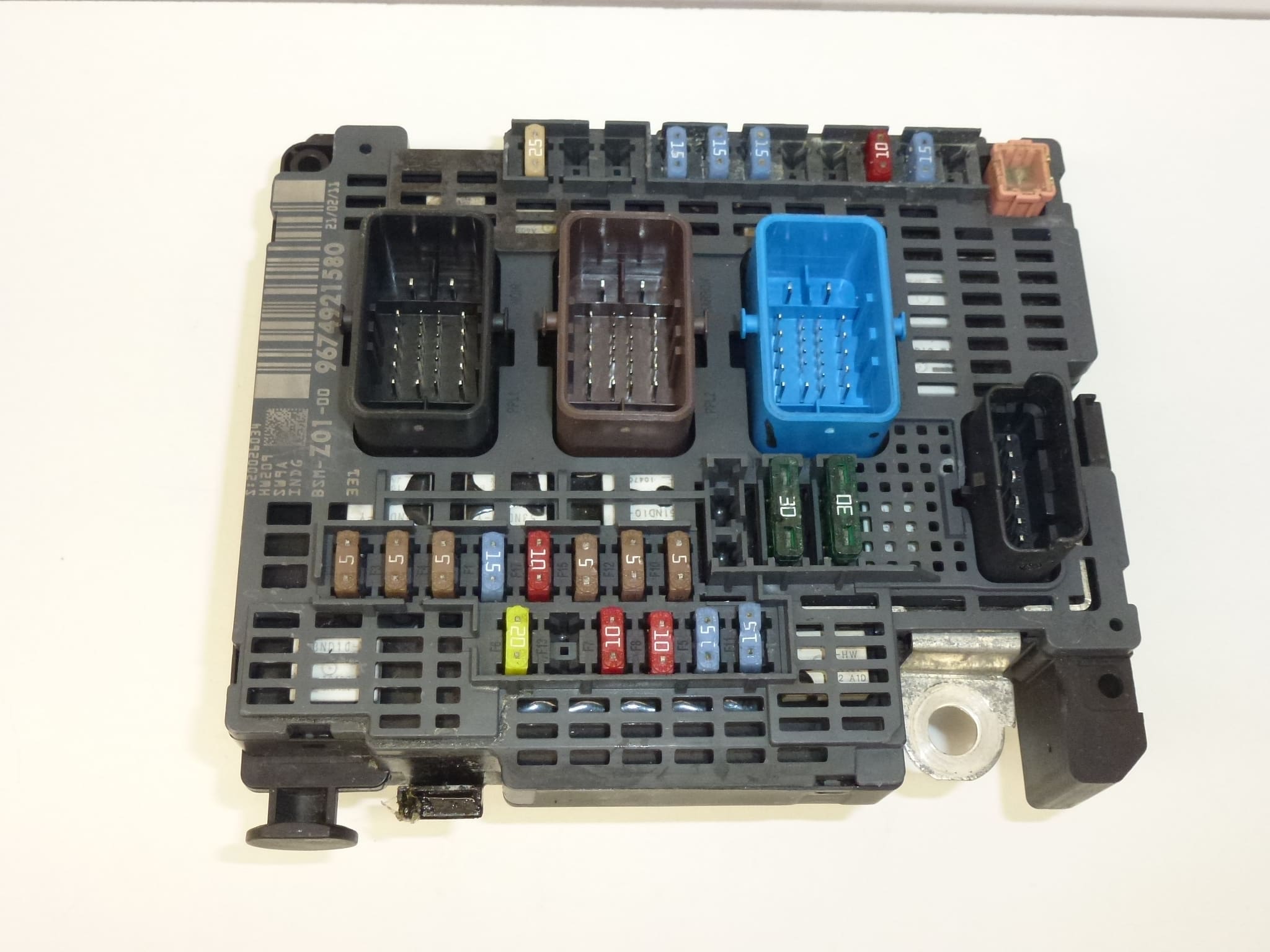
BSM Control Unit suitable for CITROËN C4 II
This used BSM (Body System/Smart Junction Box) control unit is a direct-fit replacement option for vehicles in the Stellantis Citroën/Peugeot family and is commonly searched for by part numbers. It is ideal for professional workshops and experienced DIY mechanics who need a cost-effective remedy for electrical faults originating from the engine-bay fuse/relay module. Listed reference numbers increase search visibility and help you quickly confirm compatibility when comparing parts.
Key Features And Function
The BSM combines power distribution (fuses and relays) with control logic for multiple vehicle subsystems located in the engine compartment. Typical functions include routing power to starters, fuel pumps, cooling fans and other major consumers, distributing fused circuits and managing several body-related electrical commands. In many installations the unit also interfaces with vehicle immobilizer and central control networks, so proper diagnosis and, if required, initialization may be necessary after replacement.
Technical Information
- Manufacturer: Stellantis (Citroën / Peugeot)
- Model: CITROËN C4 II
- Product Codes: 9674921580, 9807428080, 6500JL, 6500JN
- Other Numbers: Z01-00
Installation And Replacement
Replacement of the BSM is a moderate-difficulty job suited to trained technicians and experienced DIYers. Recommended general steps:
- Ensure the vehicle is parked safely with the ignition off. Disconnect the negative battery terminal before any work to prevent short circuits and protect vehicle electronics.
- Locate the BSM in the engine bay (usually under a protective cover near the firewall or inner fender). Remove any covers or trim to gain access.
- Carefully release and unplug all electrical connectors—note locking tabs and take photos if needed to ensure correct reassembly.
- Unscrew the mounting fasteners and remove the unit. Inspect connectors and wiring for corrosion or damage.
- Install the replacement unit, secure mounting bolts, reconnect all connectors and replace covers. Reconnect the battery last.
- Perform system checks: verify that lights, starter, fans and other affected circuits operate normally. If any vehicle immobilizer or key-related functions are affected, the unit may require initialization or configuration with appropriate diagnostic equipment.
Mounting Recommendations
- Always disconnect the battery before removing or installing the BSM to avoid electrical damage.
- Check connector pins and harness seals for corrosion or moisture before installation; clean and repair as needed.
- Use correct torque for mounting fasteners and ensure the unit is seated without stress on wiring to prevent vibration damage.
- After installation, run a full electrical systems check and clear any diagnostic trouble codes with suitable diagnostic tools.
Why The Part Most Often Fails
Failures are commonly caused by water ingress and corrosion, especially in vehicles exposed to road salt or with degraded seals. Thermal cycles and vibration can fatigue solder joints and internal components over time. Voltage spikes, poor battery connections and connector corrosion also lead to intermittent faults or complete failure. Proper inspection of the surrounding environment and connectors during installation greatly reduces the risk of repeated failures.
Notes For Professionals
This listing includes common OEM reference numbers to assist identification and aftermarket searching. Use a targeted diagnostic approach to confirm the BSM is the root cause of the fault before replacement—symptoms like blown fuses, multiple electrical circuits failing simultaneously or erratic engine-bay electrical behavior commonly point to the BSM.