Description
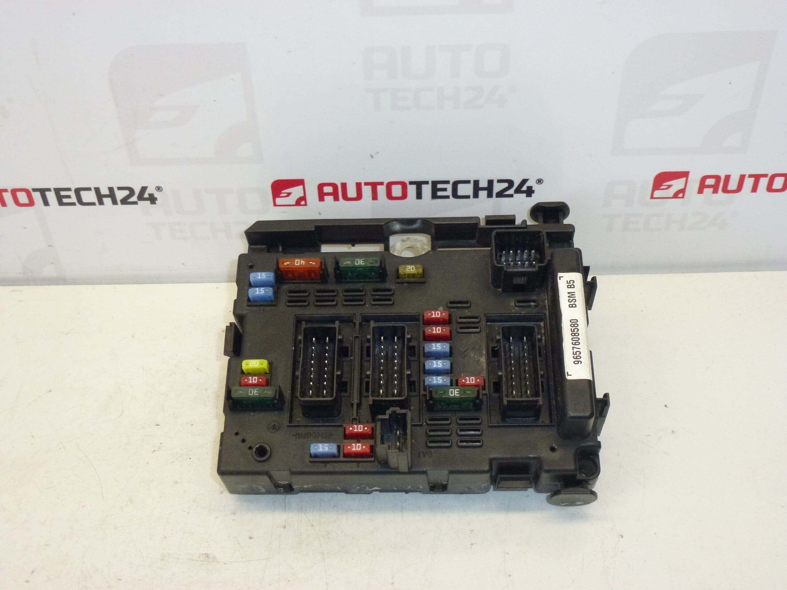
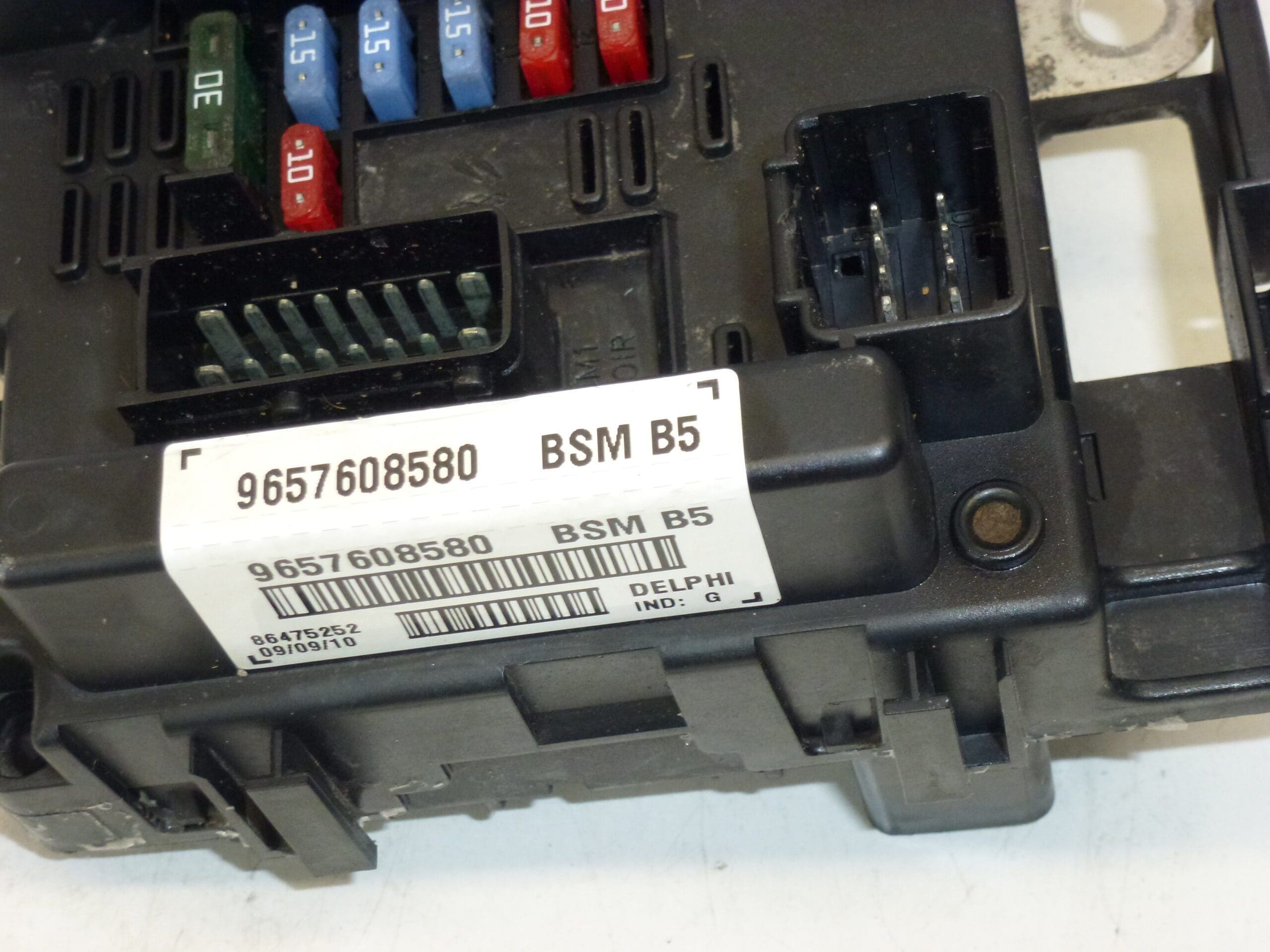
BSM B5 DELPHI control unit for Citroën and Peugeot vehicles. Some of the mounting brackets may be damaged – this does not affect functionality. This is a used part sold with a functional warranty.
Product Overview
Delphi BSM B5 body control module designed for a range of Citroën and Peugeot models. The unit is commonly referenced by part numbers 9657608580 and 6500Y1. The BSM centralizes and manages many body and comfort electrical functions, making it a frequent replacement item in older vehicles. Suitable For Professional Mechanics And Skilled DIYers Who Service Stellantis Group Cars.
Technical Information
- Manufacturer: Delphi
- Model: BSM B5
- Product Codes: 9657608580
- Other Numbers: 6500Y1
Compatible Models
Commonly Found On Or Compatible With The Following Models:
Function
The BSM (Body Systems Module) Controls Multiple Body And Comfort Functions Such As Central Locking, Interior And Exterior Lighting Management, Windshield Wiper/Washer Control, Some Convenience Relays, And Communication To Other Control Units. It Serves As A Central Node For Body Electronics, Monitoring Inputs And Switching Outputs According To Vehicle Logic.
Common Causes Of Failure
- Water Ingress Or Moisture Leading To Corrosion Of Connectors And PCB Traces.
- Connector Oxidation Or Poor Electrical Contact Resulting In Intermittent Faults.
- Thermal Stress And Age-Related Degradation Of Components.
- Voltage Spikes Or Short Circuits Causing Component Damage.
- Mechanical Damage To The Housing Or Mounting Brackets (Cosmetic Damage Often Does Not Affect Functionality).
Replacement Instructions
Replacing The BSM Requires Basic Electrical And Trim Removal Skills. Typical Steps:
- Disconnect The Battery Before Any Work To Prevent Short Circuits And Protect The Unit.
- Locate The BSM (Position Varies By Model — Often Mounted In The Engine Bay Fusebox Area Or Behind The Glovebox). Consult A Repair Manual For Exact Location.
- Remove Necessary Trim Panels And Fasteners To Access The Module.
- Unplug All Electrical Connectors Carefully, Releasing Any Safety Clips.
- Remove The Unit From Its Mounting, Transfer Any Required Brackets, Then Install The Replacement Unit.
- Reconnect Connectors Securely, Refit Panels, And Reconnect The Battery.
- Verify All Functions (Locks, Lights, Wipers, Etc.) And Clear Fault Codes With A Diagnostic Tool If Available.
Installation Recommendations
- Always Disconnect The Battery And Follow The Manufacturer’S Service Procedure To Avoid Damage.
- Inspect Connectors And Wiring For Corrosion Or Damage; Clean And Repair As Needed Before Installing The New Unit.
- Apply Dielectric Grease To Connectors To Help Prevent Future Corrosion In Moist Environments.
- Secure The Unit Firmly To Prevent Vibration Damage; Replace Any Broken Mounting Clips To Avoid Strain On Connectors.
- Use A Diagnostic Scanner To Check For Stored Faults After Replacement And To Confirm Proper Operation Of All Linked Systems.
- Address Any Source Of Water Ingress Or Wiring Chafe To Prevent Recurrence.
Why This Part Fails Most Often
The Most Frequent Failures Stem From Moisture And Corrosion Of Electrical Connections, Followed By Thermal Aging And Electrical Surges. Mechanical Damage To Brackets Is Common But Typically Cosmetic And Does Not Impact The Module’S Performance.