Description
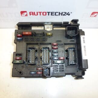
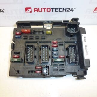
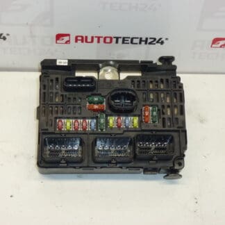
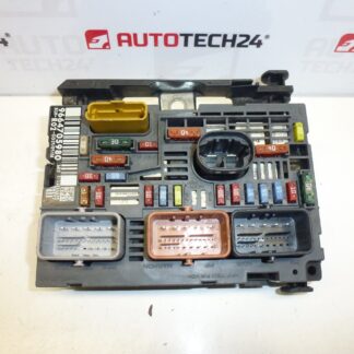
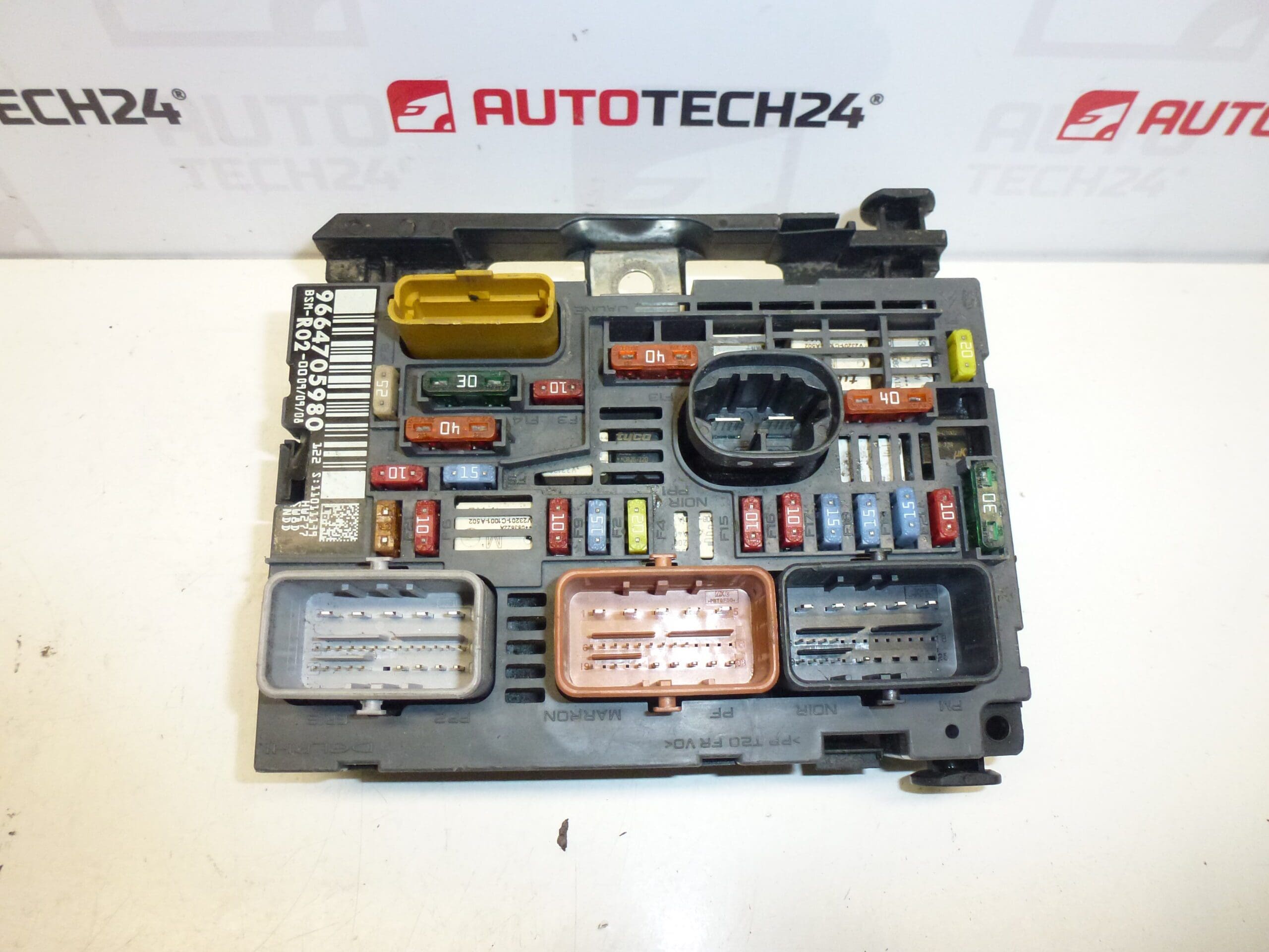
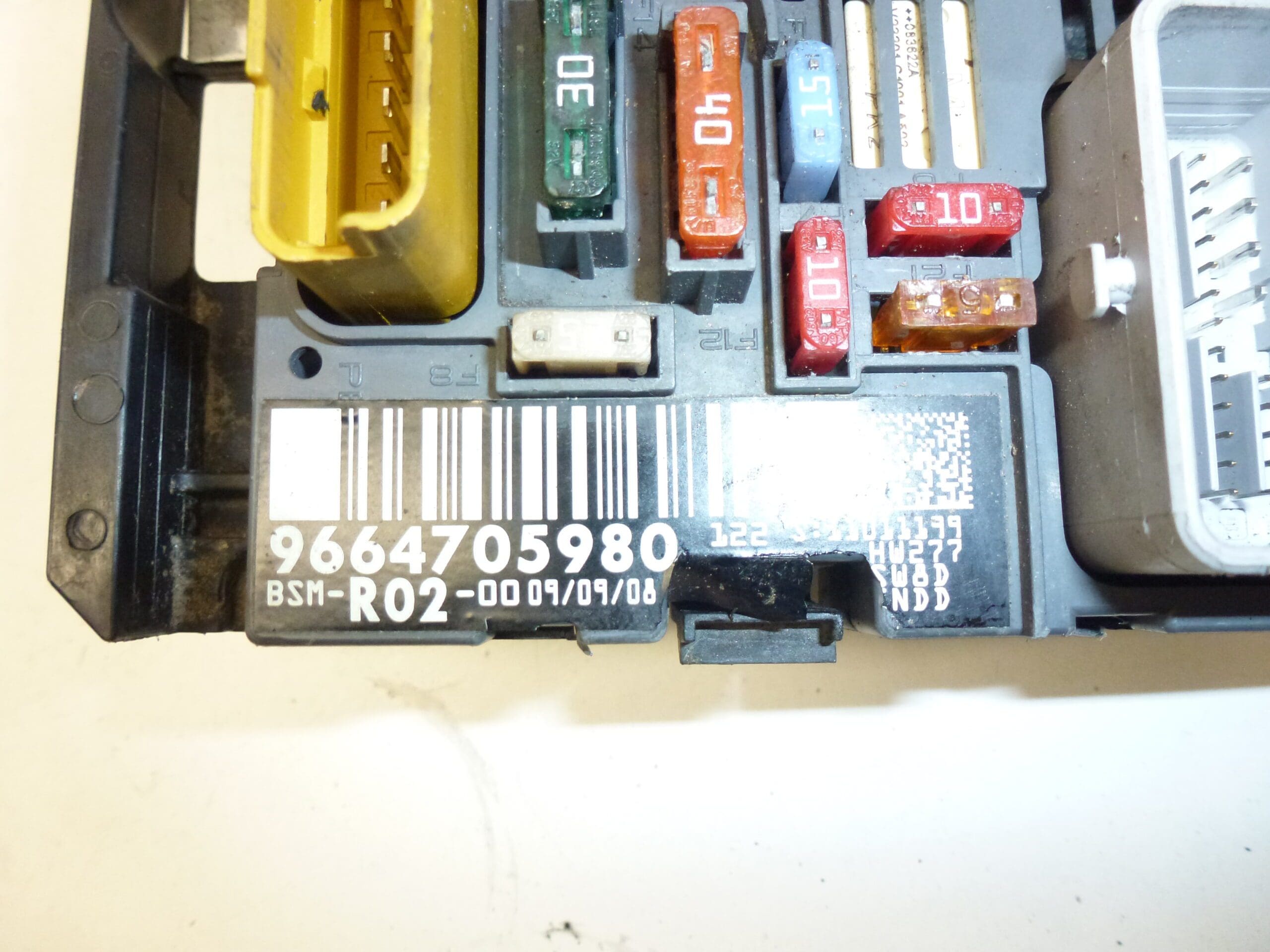
BSM Delphi R02-00 for Citroën and Peugeot vehicles. It may have a cracked mounting tab on the housing, which does not affect functionality. The unit is fully functional.
This BSM (Body Service Module) R02-00 is a direct-fit electronic control module commonly used in a range of Stellantis Citroën and Peugeot models. Supplied with original part references and cross-numbers, the unit controls and distributes power to multiple body electrical circuits and integrates with the vehicle CAN network. Ideal for professional workshops and DIY mechanics looking to replace a faulty BSM quickly and reliably. Compatible product codes and OE numbers are included below to help locate the correct replacement.
Technical Information
- Manufacturer: Delphi (reported), Siemens (reported)
- Model: BSM R02-00
- Product Codes: R02-00
- Other Numbers: 9664705980, 9807028580, 6500FQ, 6500HK
Compatibility
Commonly fitted to vehicles including (but not limited to): Peugeot 407, Peugeot 5008 I, Citroën C4 Picasso, Citroën C5 X7. Always match the module part number and connector layout to the original unit before installation.
Function And Role
The BSM acts as a central body electrical module that powers and manages multiple vehicle functions such as lighting circuits, wiper control, central locking, window and mirror functions and power distribution to auxiliary relays depending on vehicle equipment. It communicates with other on-board modules via the vehicle CAN bus and contains fuse/relay interfaces and the control electronics that handle switching and diagnostic feedback.
Installation Recommendation
- Disconnect the negative battery terminal before starting work to avoid short circuits and protect electronic modules.
- Remove necessary trim and access panels to reach the BSM housing; keep screws and clips organized.
- Carefully release electrical connectors using manufacturer-recommended tools; inspect connector pins for corrosion or damage.
- Fit the replacement unit into the original mounting position and secure fasteners. Repair or replace any broken mounting tabs if required to ensure a stable installation.
- Reconnect connectors and the battery, then perform basic function checks (lights, wipers, central locking, etc.). Some vehicles may require additional configuration or clearing of fault codes with diagnostic equipment.
- Follow the vehicle manufacturer’s procedures during removal and installation to avoid damage to the module and wiring.
Most Common Failure Reasons
- Moisture Ingress And Corrosion: Water entry into the housing or corroded connector pins can interrupt signals and power paths.
- Electrical Overload Or Short Circuits: Faulty wiring, aftermarket accessories, or power surges can damage internal electronics.
- Thermal Stress And Ageing: Repeated heat cycles and long service life may lead to component degradation.
- Mechanical Damage: Impact, vibration or broken mounting points (housing tabs) can cause poor grounding or connector strain—note: cosmetic cracks in a mounting tab do not necessarily affect module operation.
Notes On Condition
The unit may show a cracked mounting tab on the housing as noted; this cosmetic damage does not affect the electronic function of the module. The module is reported fully functional. Inspect connector integrity and surrounding wiring before installation to ensure reliable operation after fitting.