
Description
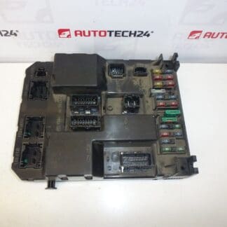
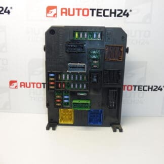
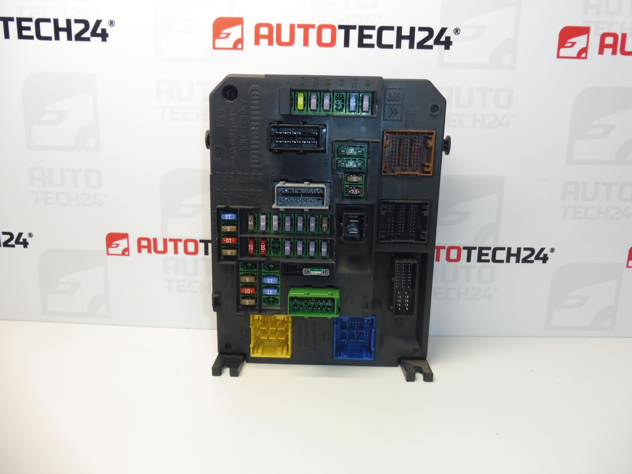
BSI-Q03-00 Continental for CITROEN C4 II cars
It is from a Citroen C4 II 2011
Part description
Used comfort unit BSI Q03-00 Continental for Citroen C4 II is intended as a spare part when repairing the car’s electronics. BSI generally provides communication between electronic systems and control of comfort functions; the specific range depends on the equipment and configuration of the vehicle.
When choosing, compare in particular the designation BSI-Q03-00, product numbers and design of the original unit. This part is listed in the documents under the numbers 9665547480, 1663372880, 6580YR and 6580YS. Matching the car model alone does not replace the comparison of design and coding requirements. With a used BSI, you need to take into account data transfer or professional adaptation to the vehicle.
Technical information
- Manufacturer: Continental
- Model: Citroen C4 II
- Type of part: BSI – comfort control unit
- Unit Designation: BSI-Q03-00
- Part numbers: 9665547480, 1663372880
- Other numbers: 6580YR, 6580YS
- Part origin: Citroen C4 II, year 2011
- Condition: used part
The year given refers to the donor vehicle, not the unit’s service life.
Product codes
- Product codes: 9665547480, 1663372880, 6580YR, 6580YS
- Type designation: BSI-Q03-00 / Q03-00
- Model: Citroen C4 II
Installation recommendations
Generally for this type of part: replacing the BSI requires proper handling of the electrical system and resolving the pairing of the unit. The following procedure is general; the exact method of disassembly, battery connection and configuration depends on the specific design of the car and the manufacturer’s service instructions.
1) Before assembly
- Compare the labels, product numbers, type designations, connectors and mounts with the old unit.
- Inspect the cover, connector cavities and contacts. Look for cracks, oxidation, moisture, deformation or signs of overheating.
- Diagnostic check if the problem is really BSI related and also check the power supply, grounding and wiring.
- If the original drive is readable, make a backup of available data and configuration in advance. Agree with an expert on how to put the replacement unit into operation before replacing it.
2) Necessary tools and materials
Usually you need the appropriate hand tools according to the connections used, tools for gently loosening the covers, a flashlight, a multimeter and PSA diagnostic equipment. Appropriate programming equipment is required to work with unit data; during diagnosis and coding, provide power according to service procedure requirements.
3) Step-by-step assembly procedure
- Record the symptoms of the defect and perform initial diagnostics. If possible, save the configuration of the original BSI.
- Prepare a way to transfer data or initialize the unit used. Without this step, don’t assume functionality after just rewiring.
- Turn off the ignition and appliances, let the electronics go to rest and disconnect the battery according to the manufacturer’s procedure.
- According to the service instructions, access the unit. Loosen the covers and clips without force.
- Document the connector connections and wiring routing so that the original arrangement can be restored.
- Unlock the connectors and disconnect them without pulling on the wires. Release the mount and remove the original drive.
- Check the connectors and the mounting area. Remove any moisture, damaged wires, or cause of overheating before installing the replacement part.
- Let a professional perform the necessary data preparation according to the chosen method. Fix the unit and connect the connectors so that their locks fit properly.
- Reconnect the battery according to the manufacturer’s instructions. Complete the initialization, configuration, and customization of keys according to your chosen deployment method.
- Perform the final diagnostics, verify the functions and return the disassembled covers after a successful check.
-
4) Post-assembly checks and function verification
Verify communication with the units, key recognition, start capability and comfort functions according to the actual vehicle equipment. Check the lights and diagnostic logs. Carry out a short test drive only after a successful static verification and without defects affecting safety; then repeat the diagnosis.
5) The most common assembly mistakes + how to avoid them
- Exchange without data preparation: solve cloning or initialization and pairing in advance.
- Disconnecting live connectors: observe the prescribed sleep of the electronics and battery disconnection.
- Untightened connector locks or bent contacts: insert the connectors straight and check their security.
- Power interruption during coding: ensure a stable power supply according to the requirements of the equipment used.
- Unremoved original cause of failure: check wiring, power supply and possible leaks before replacement.
Assembly and Coding – Important
- The unit is used and is “paired” to the original car (VIN/PIN/keys).
- Commissioning options:
- Cloning data from the old drive (EEPROM/Flash) – after the clone, the drive is plug and play.
- Virginization and subsequent initialization/telecoding via DiagBox (possibly online) + customization of keys.
- Recommended to be performed by an expert with PSA service equipment (DiagBox/Lexia/PP2000).
- Always disconnect the battery before disassembly/assembly and follow the manufacturer’s procedure to avoid damaging the unit.
Reasons why the part is damaged
For BSI comfort control units, common causes of damage include the following influences; this is not a description of the detected defects of this piece:
- Moisture and leaks which can cause corrosion of contacts and electronics.
- Short circuits in wiring or connected circuits which may overload the unit outputs.
- Overvoltage, reverse polarity or incorrect handling of the power supply, especially when interfering with the electrical system.
- Overheating and aging of electronic components which can lead to irregular or permanent blackouts.
- Unprofessional interventions or interrupted programming which can damage electronics or corrupt stored data.