Description
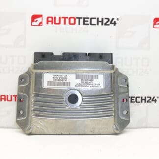
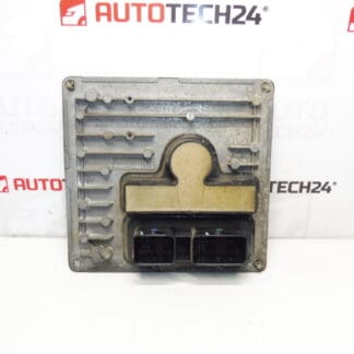
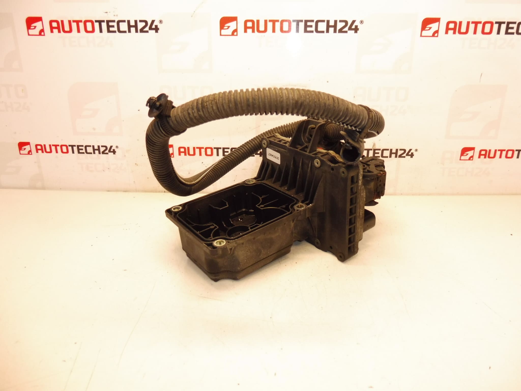
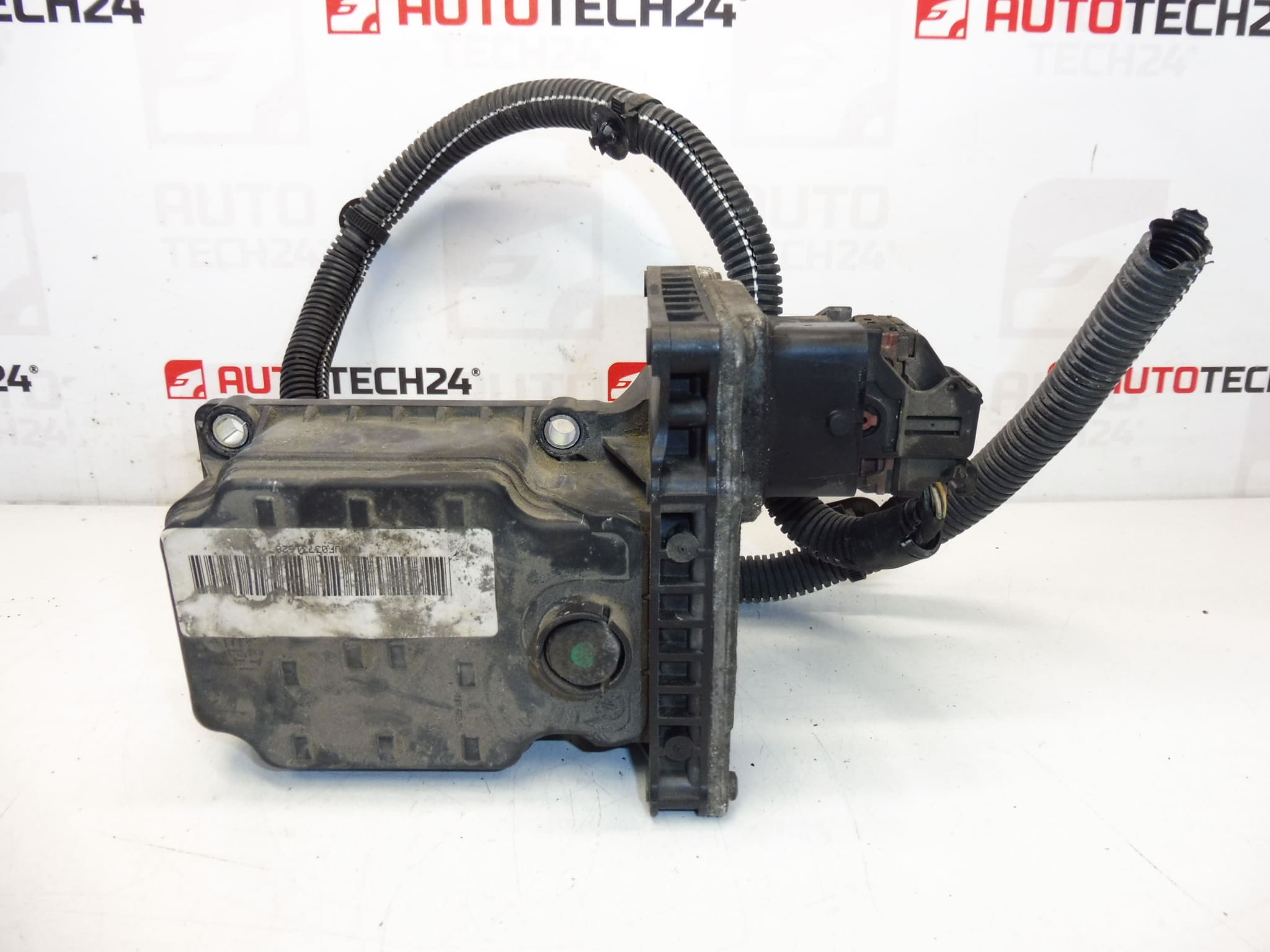
Transmission control unit MM_BVMP_MCP_CEM0 for Citroën C4 Picasso or C4 Grand Picasso. !!!! Warning: Cannot be used on C4 Hatchback !!!! Transmission harness 2529X2 can also be purchased from us. Supplied with part of the main vehicle wiring. Tested – fully functional.
Product Overview
This gearbox ECU is designed for robotized (automated manual) transmissions fitted to Citroën C4 Picasso and C4 Grand Picasso models. It manages gear selection and clutch actuation in cooperation with the transmission wiring harness and hydraulic/electric actuators. Ideal for professional workshops and experienced DIY mechanics who need a direct replacement unit identified by common part numbers (see Technical Information below).
Key Benefits
- Direct fit for compatible Citroën C4 Picasso / Grand Picasso vehicles (see compatibility).
- Comes with a portion of the main vehicle wiring harness for easier installation.
- Replaces faulty transmission ECU to restore proper gear selection, smooth shifts and clutch control.
- Commonly searched by product numbers 9664870880, 2529YC, 2531A7, 2529X2 — increasing findability in parts searches.
Technical Information
- Manufacturer: Stellantis / Citroën
- Model: MM_BVMP_MCP_CEM0 (Robotized Transmission ECU)
- Product Codes: 9664870880, 2529YC, 2531A7
- Other Numbers: 2529X2 (transmission harness)
Fits Vehicles
Intended for: Citroën C4 Picasso and Citroën C4 Grand Picasso models equipped with the MM_BVMP_MCP_CEM0 robotized gearbox control system. Not compatible with Citroën C4 Hatchback — do not attempt installation on hatchback variants.
How It Works
The ECU controls electro-hydraulic components responsible for gear selection and clutch engagement in the robotized manual transmission. It processes inputs from speed and position sensors, clutch and shift actuators, then drives solenoids/motors to perform automated shifts. Proper function depends on intact wiring, working actuators and correct software/parameter configuration.
How To Replace (Overview)
- Prepare Work Area: Park vehicle on a level surface, engage parking brake and open bonnet/trunk as required to access ECU location.
- Safety First: Disconnect the negative battery terminal before starting to avoid electrical damage.
- Access Unit: Locate the gearbox ECU — usually mounted near the transmission or inside the engine bay depending on vehicle configuration. Remove trim or protection panels if necessary.
- Disconnect Connectors: Carefully release locking tabs and unplug all electrical connectors. Inspect connectors for corrosion or damaged pins.
- Remove Unit: Unbolt and remove the old ECU. Fit the replacement unit and secure to the original mounting points with correct torque values.
- Reconnect Wiring: Reattach the supplied section of main wiring harness and all connectors, ensuring proper seating and locking of terminals.
- Power Up and Initialize: Reconnect the battery. The unit may require initialization/adaptation via a PSA diagnostic tool (DiagBox/Lexia/PP2000) to synchronize with vehicle sensors, actuators and immobilizer systems.
- Final Checks: Clear fault codes, perform system tests and road test to confirm correct shifting and clutch operation.
Installation Recommendations
- Always Disconnect Battery: Before any removal or installation, disconnect the negative battery terminal to prevent damage to the ECU or vehicle electrical system.
- Inspect Wiring And Actuators: Replace or repair any damaged wiring, corroded connectors or faulty actuators before installing the new ECU to avoid recurring faults.
- Use Proper Diagnostic Tools: After fitting, perform adaptation/coding and fault code clearing with PSA-compatible diagnostic equipment (DiagBox / Lexia / PP2000) where required.
- Professional Assistance: If you are unsure about electrical diagnostics or adaptation procedures, have the final commissioning performed by a qualified technician with PSA service tools.
Most Common Reasons For Failure
- Water Ingress Or Corrosion: Moisture on connectors or inside the unit leads to short circuits and intermittent faults.
- Wiring Harness Damage: Mechanical damage, chafing, or rodent chewing can interrupt signals between ECU and actuators/sensors.
- Actuator Or Sensor Failure: Faulty shift or clutch actuators and associated sensors can overload or confuse the ECU, leading to error states.
- Electrical Surges Or Poor Grounds: Voltage spikes, jump-starting errors or bad ground connections can damage internal electronics.
- Software/Configuration Issues: Mismatched programming or missing initialization may prevent correct operation after replacement.
What You Get
Replacement gearbox ECU MM_BVMP_MCP_CEM0 compatible with Citroën C4 Picasso / Grand Picasso, supplied with part of the main vehicle wiring harness. Unit is presented as fully functional. Verify connectors and vehicle configuration during installation.
Tags / Search Terms
ECU, Gearbox ECU, Robotized Transmission, Citroën C4 Picasso, C4 Grand Picasso, 9664870880, 2529YC, 2531A7, 2529X2