Description
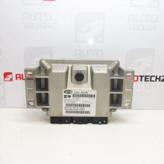
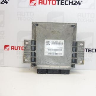
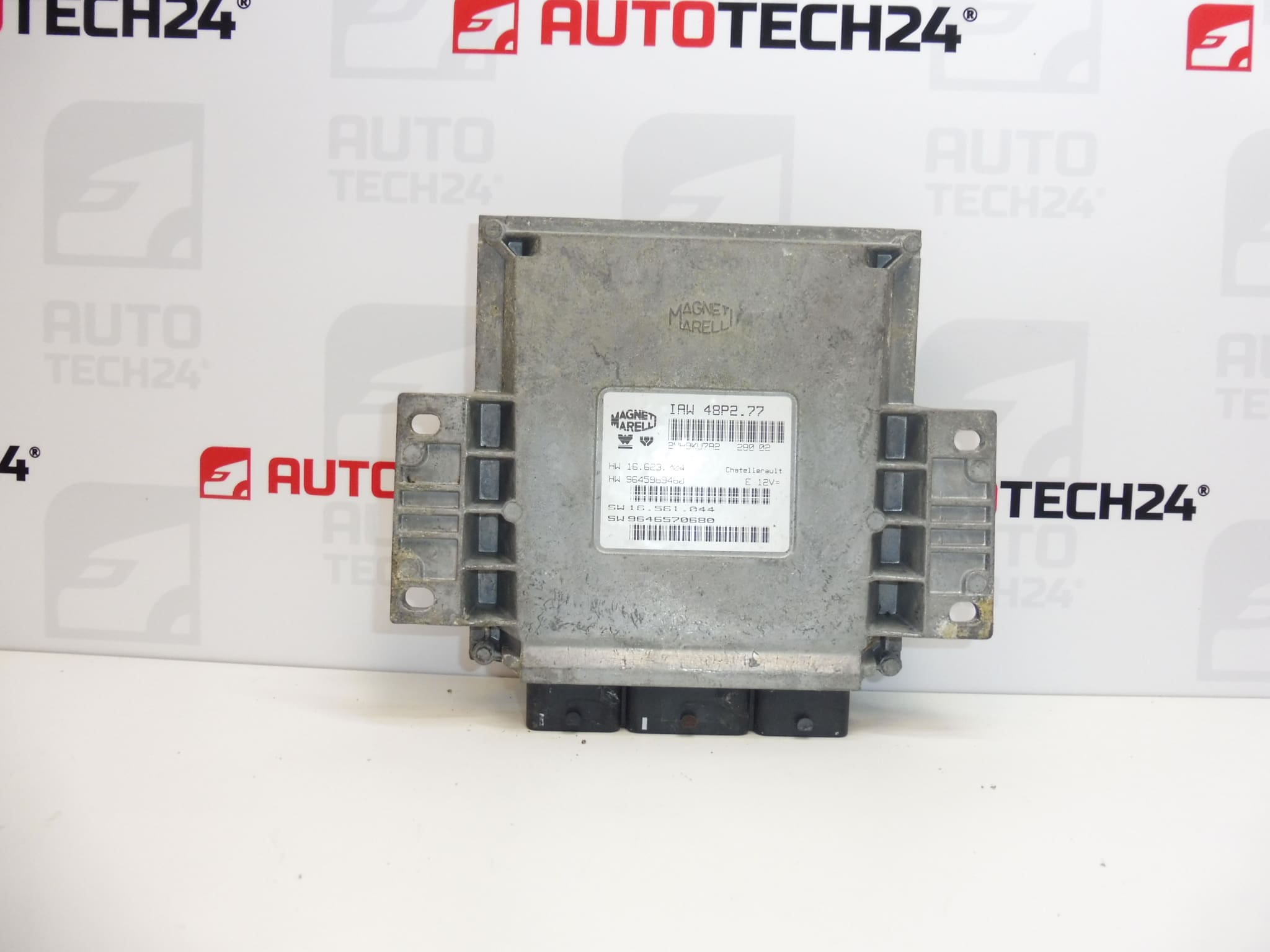
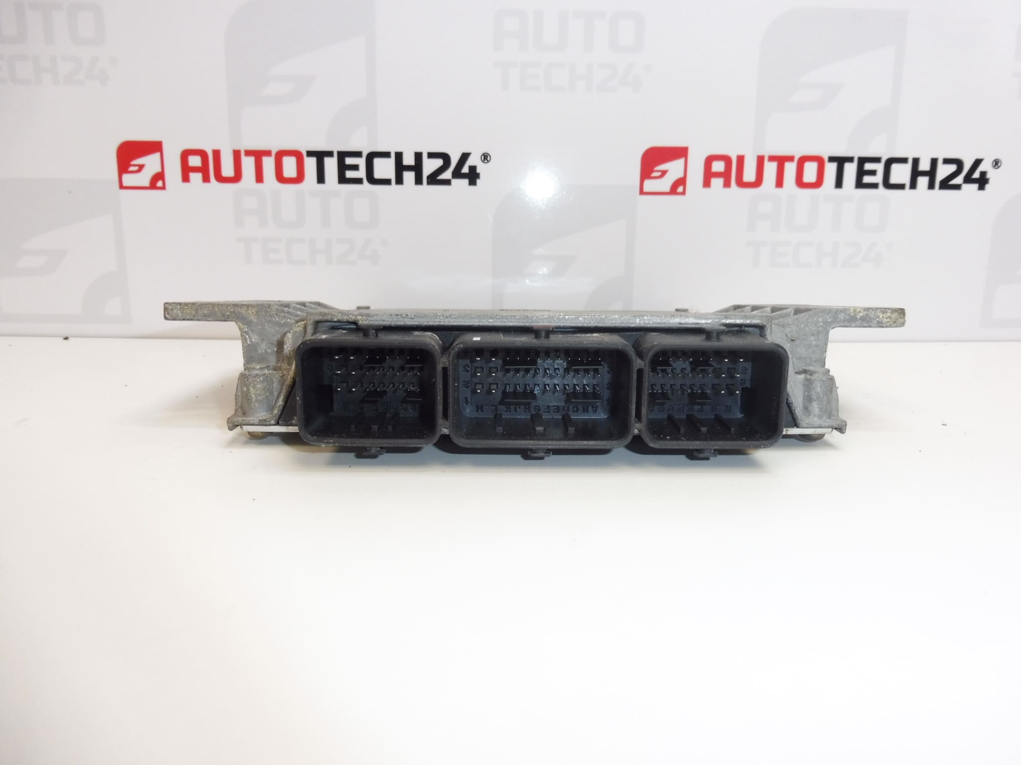
MAGNETI MARELLI IAW 48P2.77 control unit
From a PEUGEOT 206 1.1i
Part description
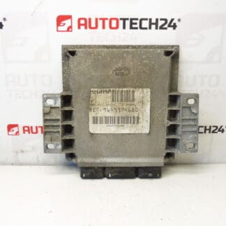
This used MAGNETI MARELLI IAW 48P2.77 fuel injection control unit comes from a Peugeot 206 1.1i. This type of unit processes sensor data and controls fuel injection and related engine functions. When replacing it, the correct unit variant and its electronic adaptation to the vehicle are important.
When selecting a replacement part, compare the designation IAW 48P2.77 and the numbers 9646570280, 9645989480 and 1938NH with the original unit. The stated origin of the part alone does not confirm compatibility with all Peugeot 206 vehicles. This is a repair solution using a used part; before replacement, it is advisable to confirm through diagnostics that the fault is actually caused by the unit rather than the power supply or wiring.
Technical information
- Manufacturer: MAGNETI MARELLI
- Model: Peugeot 206
- Unit type: IAW 48P2.77
- Part category: fuel injection control unit
- Part origin: PEUGEOT 206 1.1i
- Condition: used part
- Additional numbers: 9646570280, 9645989480, 1938NH
- Additional designation in the documentation: NFP
Product codes
- Product codes: 9646570280, 9645989480, 1938NH
- Unit designation: IAW 48P2.77
- Model: Peugeot 206
Installation recommendations
The following procedure is a general guide to replacing a fuel injection control unit. The exact steps for removal, power disconnection and commissioning depend on the specific vehicle variant and the manufacturer’s service instructions. Simply connecting a used unit may not allow the engine to start.
1) Before installation
- Compare the type designation, product numbers, connectors and mountings with the old unit. Assess the required hardware and software compatibility using the service data.
- Inspect the housing, contacts and connector locks. Pay attention to corrosion, moisture, bent pins and signs of overheating.
- Check the vehicle’s power supply, ground connections and wiring. An unresolved circuit fault can also damage the replacement unit.
- Choose the data transfer or initialization method in advance. If possible, save the diagnostic information and back up the original unit’s data.
2) Required tools and materials
- Standard hand tools suitable for the fasteners used, and tools for gently releasing connectors.
- A multimeter and diagnostic equipment suitable for the vehicle.
- Equipment for backing up, cloning or initializing the unit, depending on the chosen method.
- A clean, dry workspace and suitable protection for the electronics against electrostatic discharge.
3) Step-by-step installation procedure
- Perform initial diagnostics and record the fault symptoms and available data from the original unit.
- Confirm the replacement unit’s compatibility by comparing designations and service data. Choose the procedure for putting it into operation.
- Switch off the ignition, allow the electronic systems to enter their standby state according to the manufacturer’s instructions, and disconnect the battery using the prescribed procedure.
- Access the unit according to the service procedure for the specific vehicle. Before disconnecting anything, record the wiring routing and connector connections.
- Release the connector locks without force. Do not pull on the wires, and protect the contacts from dirt and moisture.
- Undo the mountings and remove the original unit. Check the surrounding wiring and eliminate any cause of water ingress or damage.
- Depending on the chosen method, have a specialist transfer the data or prepare the replacement unit for subsequent initialization. The sequence of programming operations depends on the equipment used.
- Position the replacement unit and secure it according to the manufacturer’s instructions. The wiring must not be stretched or pinched.
- Connect and fully lock the connectors. Check that they are seated correctly and refit all protective components that were removed.
- Connect the battery using the prescribed procedure. Complete the necessary coding, adaptation and diagnostic checks before starting the engine.
4) Post-installation checks and functional verification
Verify communication with the unit, correct configuration and start authorization. After starting, monitor engine operation, warning lights and diagnostic data. If everything is in order and the vehicle is safe to operate, carry out a short test drive and then read the fault memory again. Address persistent problems through diagnostics rather than repeatedly replacing parts blindly.
5) Common installation mistakes and how to avoid them
- Selecting solely by vehicle model: also compare the unit’s designation and technical specifications.
- Skipping adaptation: determine how the unit will be put into operation before replacing it.
- Working with the power connected: follow the manufacturer’s battery disconnection procedure.
- Damaging contacts: insert connectors straight and do not force them to lock.
- Leaving the original cause of the fault unresolved: repair damaged wiring, power supply faults or the source of moisture before connecting the replacement part.
Installation and coding – important
- The unit is used and is “paired” with the original vehicle (VIN/PIN/keys).
- Options for putting it into operation:
- Cloning data from the old unit (EEPROM/Flash) – after cloning, the unit is plug and play.
- Virginization followed by initialization/telecoding via DiagBox (online if required) + key adaptation.
- It is recommended that this be carried out by a specialist with PSA service equipment (DiagBox/Lexia/PP2000).
- Always disconnect the battery before removal/installation and follow the manufacturer’s procedure to avoid damaging the unit.
Reasons why the part may become damaged
In general, fuel injection control units can be damaged by the following factors; this is not a description of the observed condition of this particular unit:
- Moisture and corrosion after the protection of the unit or connectors has been compromised.
- Overvoltage or improper handling of the power supply, for example when the battery is connected incorrectly.
- Short circuits in the wiring or connected components, which can damage the unit’s output circuits.
- Thermal stress and vibration, which place long-term strain on electronic components and connections.
- Improper interventions and interrupted programming, which can damage the electronics or corrupt stored data.