Description
Control Unit – Automatic Headlamp Leveling Unit For CITROËN C4 And C5 II
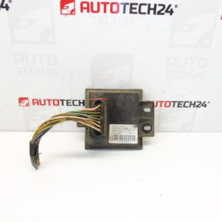
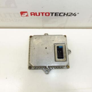
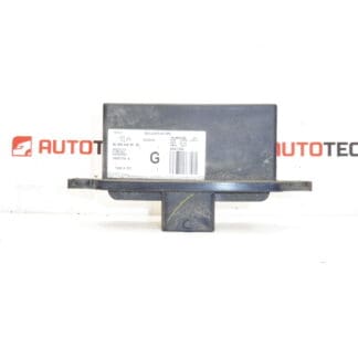
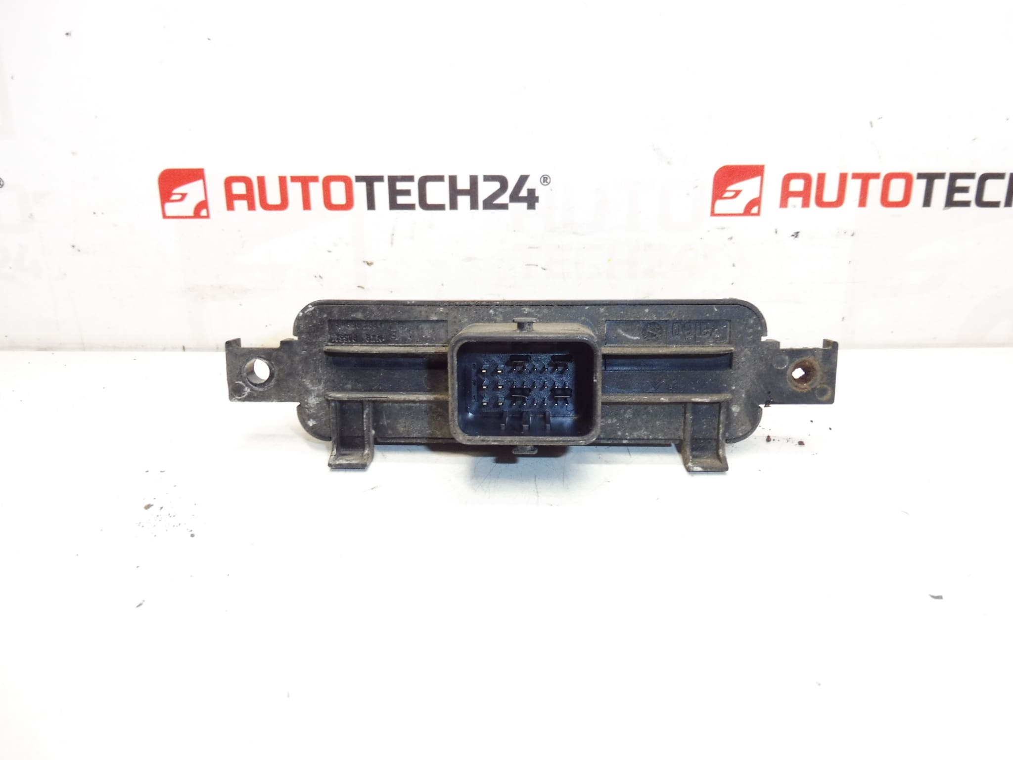
Valeo headlight control unit designed for automatic headlamp leveling on selected Citroën models. This electronic module manages the vertical aim of Xenon headlamps, ensuring correct beam alignment under varying vehicle loads and driving conditions. Frequently searched by part numbers, this unit is listed under 9658054280 and 6224K8 and is suitable for technicians and experienced DIY motorists working on Citroën C4 and C5 II vehicles.
The module interfaces with suspension or height sensors and the headlamp actuators to maintain legal and safe illumination. Replacing a faulty unit restores proper headlight alignment, reduces glare for oncoming traffic and eliminates dashboard warnings related to the headlamp system. Ideal for garages, body shops and independent mechanics who require a direct-fit electronic control unit from a recognized supplier.
Technical Information
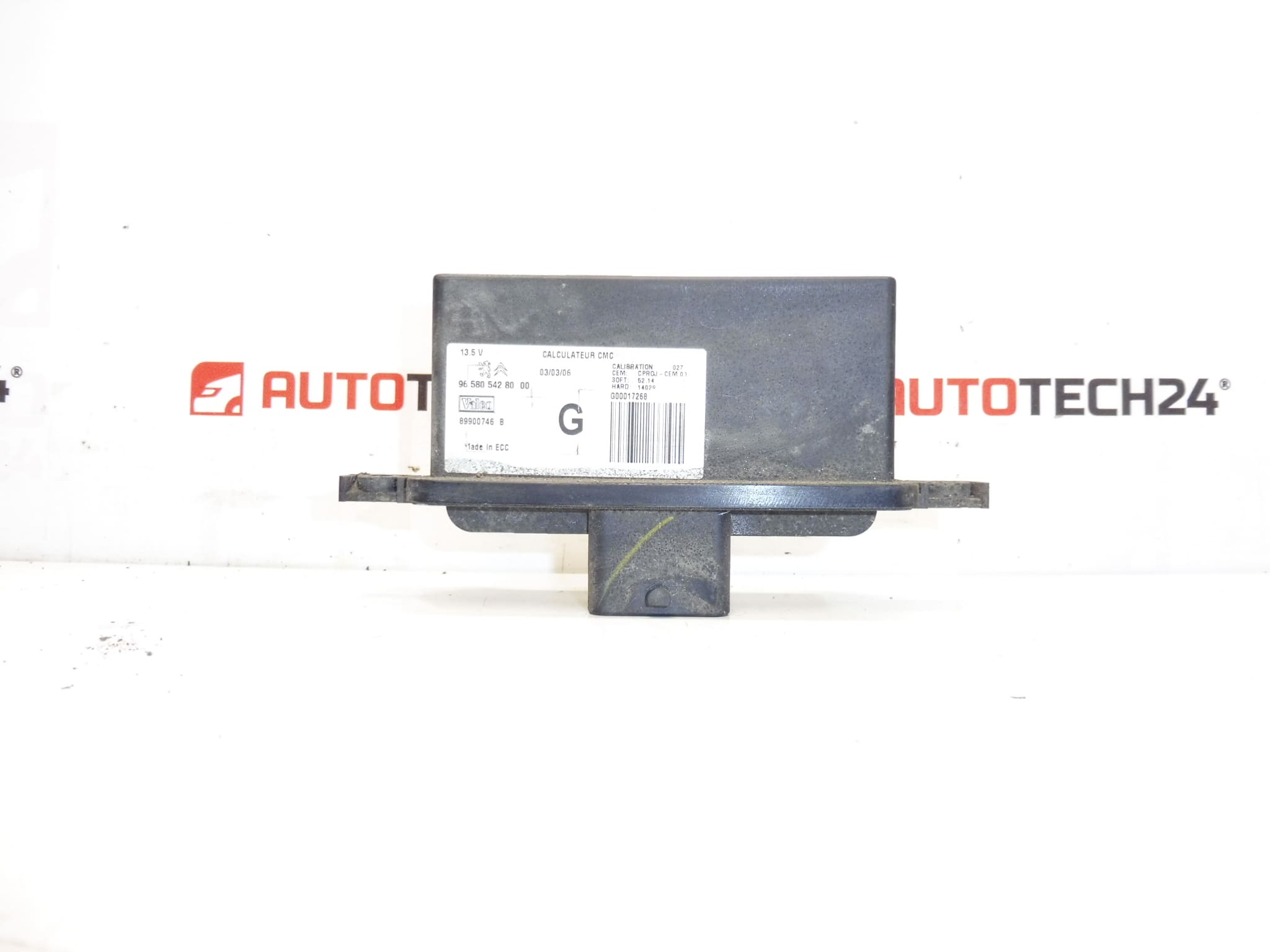
- Manufacturer: Valeo
- Model: Citroën C4; Citroën C5 II
- Product Codes: 9658054280, 6224K8
- Additional Numbers: 6224R6, 6224R5, NFP
Installation Recommendations
- Disconnect The Battery Before Starting Work To Avoid Short Circuits And Unintended Airbag/Body Control Reactions.
- Locate The Unit—It Is Often Mounted Near The Headlamp Assembly Or Inside The Engine Bay Close To The Front Wiring Harness; Remove Any Protective Covers Or Brackets.
- Carefully Unplug Electrical Connectors And Inspect For Corrosion Or Bent Pins; Clean Connectors If Necessary Before Fitment.
- Mount The Replacement Unit Securely Using The Original Fasteners; Ensure Gaskets Or Seals Are Correctly Seated To Prevent Moisture Ingress.
- Reconnect The Battery And Cycle Ignition; Verify Headlamp Leveling Operation. Note: Some Vehicles Require Adaptation Or Calibration Via A Diagnostic Tool After Replacement.
- After Installation, Verify Proper Beam Aim On A Level Surface Per Local Regulations And Test Drive To Confirm Automatic Correction Functionality.
Common Failure Causes
- Moisture Ingress And Corrosion—Water Penetration Into The Unit Or Connectors Is A Frequent Cause Of Failure, Especially In Older Headlamp Assemblies Or Vehicles Exposed To Road Salt.
- Electrical Surges Or Faulty Wiring—Shorts, Poor Grounds Or Damaged Wiring Can Damage Internal Electronics.
- Mechanical Wear—Worn Headlamp Actuators Or Height Sensors Can Place Excessive Load On The Module, Leading To Premature Failure.
- Thermal Stress—Repeated Heating And Cooling Cycles In The Engine Bay May Degrade Components Over Time.
This control unit is a direct-replacement part commonly referenced by its part numbers (9658054280 / 6224K8). When ordering, confirm the part code matches the unit being replaced to ensure fitment. Suitable For Professional Repair Shops And Competent DIYers Comfortable With Vehicle Electrical Systems.
Order now to restore correct headlamp leveling and eliminate related dashboard warnings—ideal for maintaining safe nighttime visibility and compliance with road safety standards.