Description
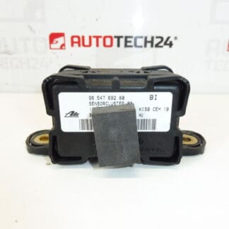
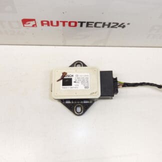
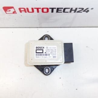
Bosch ESP Kinematic Sensor For Citroën C4 Picasso, C5 X7 And Peugeot 308, 3008, 5008 And Others
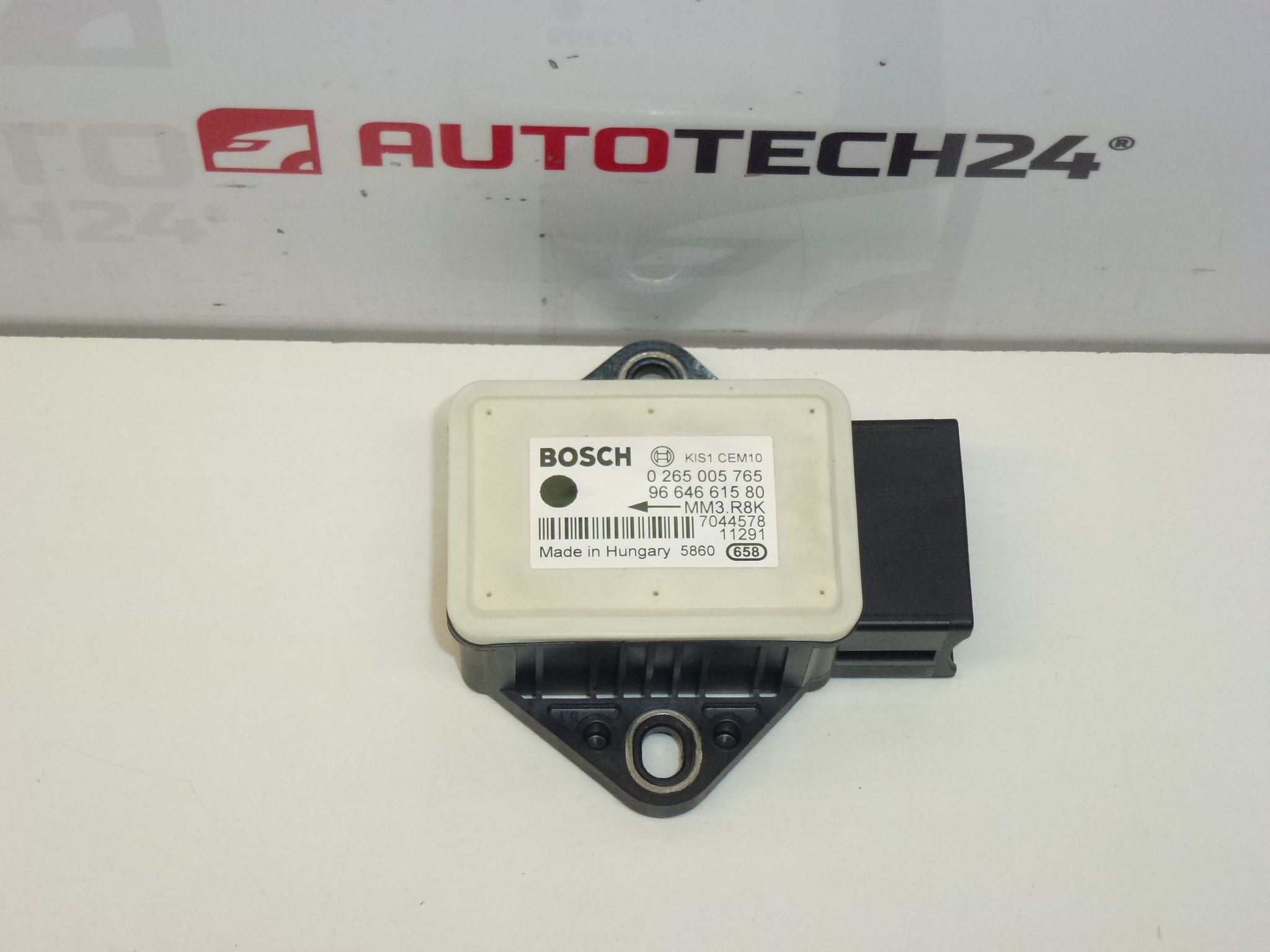
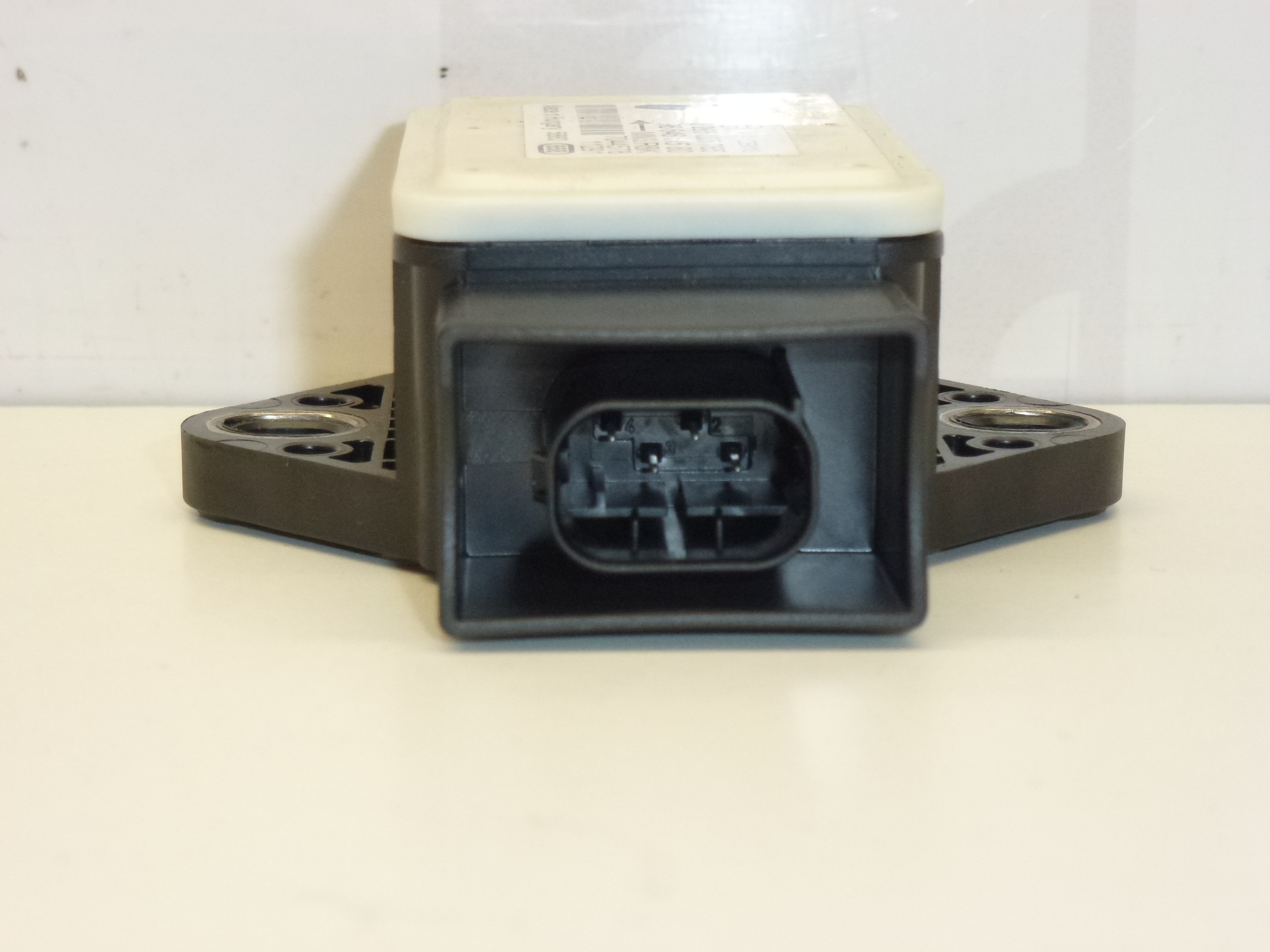
This Bosch ESP kinematic (yaw rate) sensor is a direct-fit component for the stability control system on selected Citroën and Peugeot models. It provides the Electronic Stability Program (ESP) with real-time data on vehicle rotation to help the ABS and traction control systems maintain directional stability during cornering and emergency manoeuvres. Suitable for professional workshops and competent DIY mechanics who identify parts by manufacturer numbers.
Key Features And Benefits
- Direct Replacement For Factory-Fitted Bosch Sensors On Compatible Citroën And Peugeot Models.
- Accurate Yaw Rate Measurement To Support ESP, ABS And Traction Control Functions.
- Part-Number Based Identification Reduces Diagnostic Time When Replacing A Faulty Sensor.
- OEM-Style Mounting And Electrical Interface For Reliable Fitment.
Compatible Models
Citroën C4 Picasso, Citroën C5 X7, Peugeot 308, Peugeot 3008 I, Peugeot 5008 I And Other Stellantis Vehicles Using The Listed Part Numbers.
Symptoms Of A Failing Sensor
- ESP/ABS/Traction Control Warning Light Illuminated On The Dashboard.
- Loss Or Interruption Of Electronic Stability Assistance During Cornering.
- Intermittent Fault Codes Or Communication Errors Related To Yaw Rate Input.
- Unpredictable Vehicle Behaviour Or Reduced Stability On Slippery Surfaces.
Mounting Recommendations
- Always Disconnect The Battery Before Starting Work And Follow Manufacturer Removal/Installation Procedures To Avoid Damage.
- The Sensor Is Typically Mounted Near The Vehicle Centreline (Under The Centre Console Or On The Transmission Tunnel) Depending On Model; Remove Interior Trim Carefully To Access The Unit.
- Handle The Sensor Carefully, Avoid Mechanical Shock And Contamination; Secure Using Original Mounting Points And Tighten Fasteners To Manufacturer Specification.
- Inspect And Clean Connector Pins And Wiring Loom; Repair Any Corroded Or Damaged Wiring Prior To Installation.
- After Installation Perform Steering Angle Sensor Calibration And ESP/ABS System Initialization Using A Suitable Diagnostic Tool (DiagBox Or Equivalent) To Ensure Correct Operation.
- Complete A Controlled Road Test To Verify Stability Control Functionality.
Why This Part Fails Most Often
- Moisture Ingress And Corrosion Affecting The Sensor Housing Or Electrical Connector.
- Mechanical Damage From Impacts Or Excessive Vibration.
- Electrical Faults Such As Short Circuits, Open Wires Or Poor Grounding.
- Ageing Electronics Leading To Signal Drift Or Intermittent Failures.
Technical Information
- Manufacturer: Bosch
- Model: Citroën C4 Picasso; Citroën C5 X7; Peugeot 308; Peugeot 3008 I; Peugeot 5008 I
- Product Codes: 9664661580, 0265005765
- Other Numbers: 454949, 9811627180, 265005765
Helpful Tip: When customers search by part number (e.g. 9664661580, 0265005765, 454949), matching the code in the listing increases visibility and speeds up correct part selection.