Description
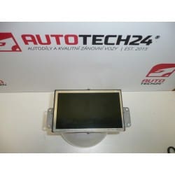
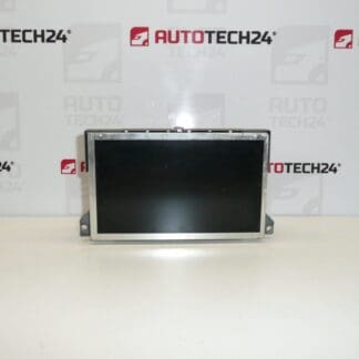
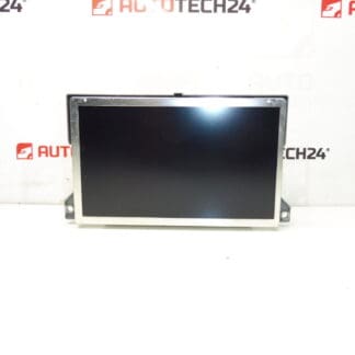
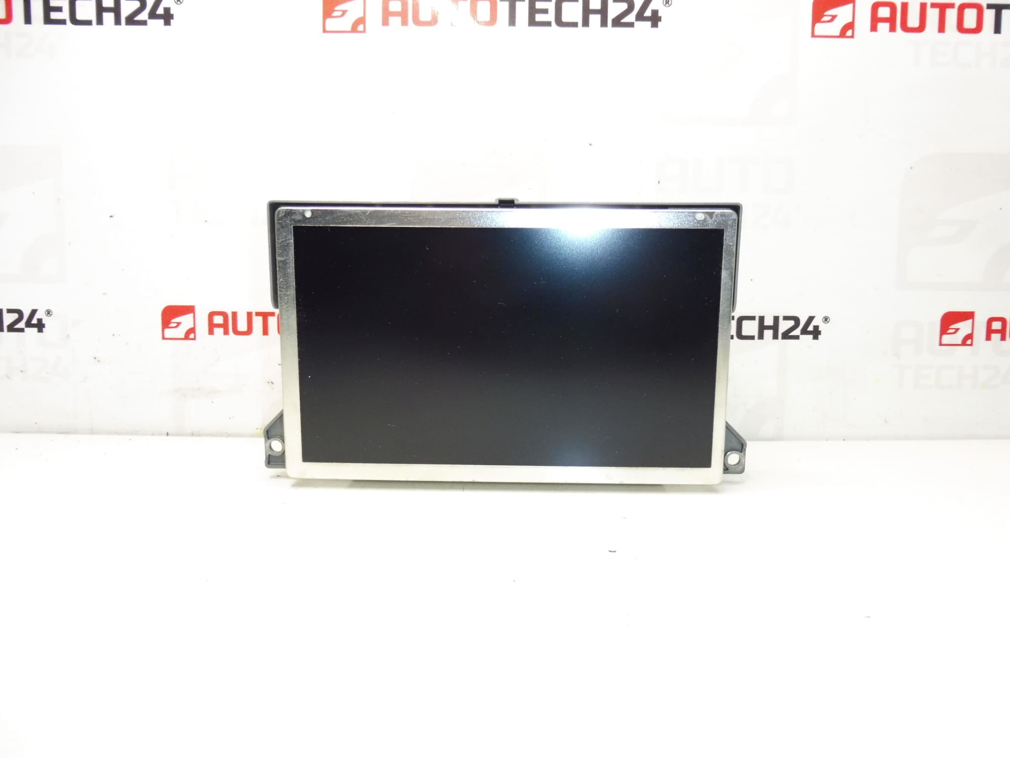
Display for radio, navigation and heating for Citroën C5 II. Shows radio, navigation, trip computer, suspension, climate control and other vehicle functions. Fully functional, tested.
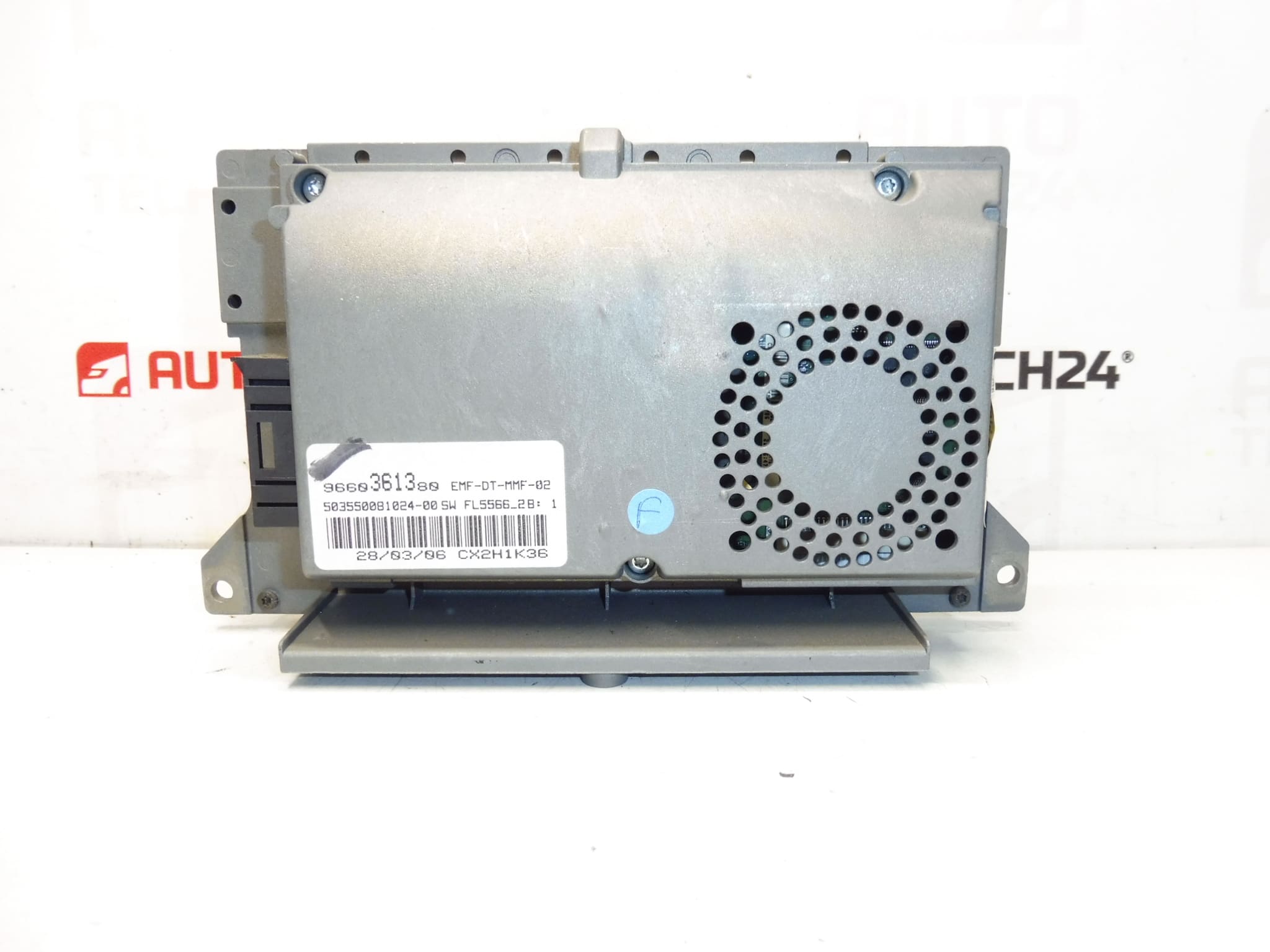
This instrument display is a direct-fit unit for Citroën C5 II vehicles and is commonly sought under the part numbers 9660361380 and 6563YK (NFP). Ideal for professional workshops and DIY mechanics, the module restores clear visualization of audio, navigation and vehicle system information, helping diagnose and operate in-car systems reliably.
The display presents radio information, navigation maps and directions, trip computer data, suspension/comfort system messages and climate control settings on a single readable screen. Clear contrast and legible characters improve in-cabin ergonomics and reduce time spent interpreting fault messages during diagnostics. Including the correct part number in your search (9660361380, 6563YK) will help you find the compatible unit faster.
Technical Information
- Manufacturer: Stellantis (Citroën/Peugeot)
- Model: Citroën C5 II
- Product Codes: 9660361380, 6563YK
- Additional Numbers: NFP
Installation Recommendations
- Disconnect Battery: Always isolate the vehicle battery before starting to avoid short circuits and to protect electronic modules.
- Remove Trim Carefully: Use trim tools to remove the center dash bezel without damaging clips. Work on a clean, well-lit bench.
- Access Unit: Unscrew and slide out the radio/navigation unit to reach the display connector. Note screw locations for reassembly.
- Disconnect Connectors: Unplug multi-pin connectors and ribbon cables with care; do not force bent pins or folded flat cables.
- Swap Display: Replace the display module, ensuring connectors and ribbon cables seat fully. Reassemble in reverse order and reconnect the battery.
- Post-Installation Check: Verify screen illumination, button responsiveness and that navigation/audio menus appear correctly. Perform basic system reset if required.
Most Common Failure Reasons
- Backlight Degradation: Over time the display backlight can dim or fail, causing unreadable text in sunlight or low brightness.
- Connector/Ribbon Cable Faults: Broken or loose ribbon cables and corroded connectors produce flicker, lines or total loss of image.
- Pixel Defects And Panel Wear: Dead pixels, vertical/horizontal lines or patchy contrast appear with ageing panels.
- Moisture Ingress And Corrosion: Water exposure or humidity can corrode contacts or short internal circuitry.
- Software/Boot Errors: Intermittent blank screens or error messages can be caused by firmware faults or interrupted updates.
Expected Service Life: Service life varies with use and environment; many displays remain functional for 8–15 years. Symptoms that indicate replacement include persistent blank screen, vertical/horizontal lines, loss of backlight or intermittent operation.
Why Choose This Unit: Direct-fit compatibility with Citroën C5 II and clear listing under 9660361380 and 6563YK make this display an efficient replacement for restoring full instrument and navigation readability. Suitable for professional installation or experienced DIY mechanics familiar with dashboard electronics.