Description
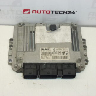
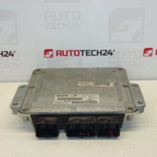
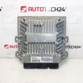
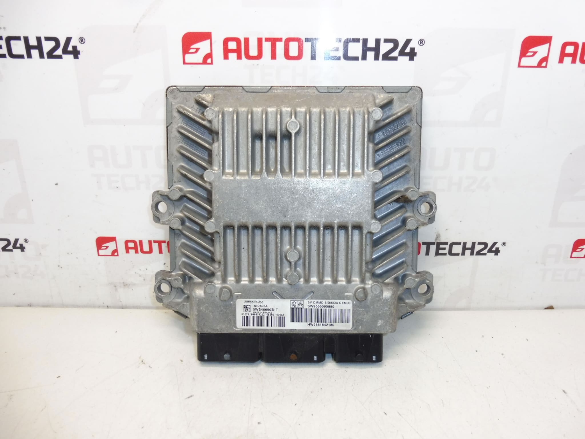
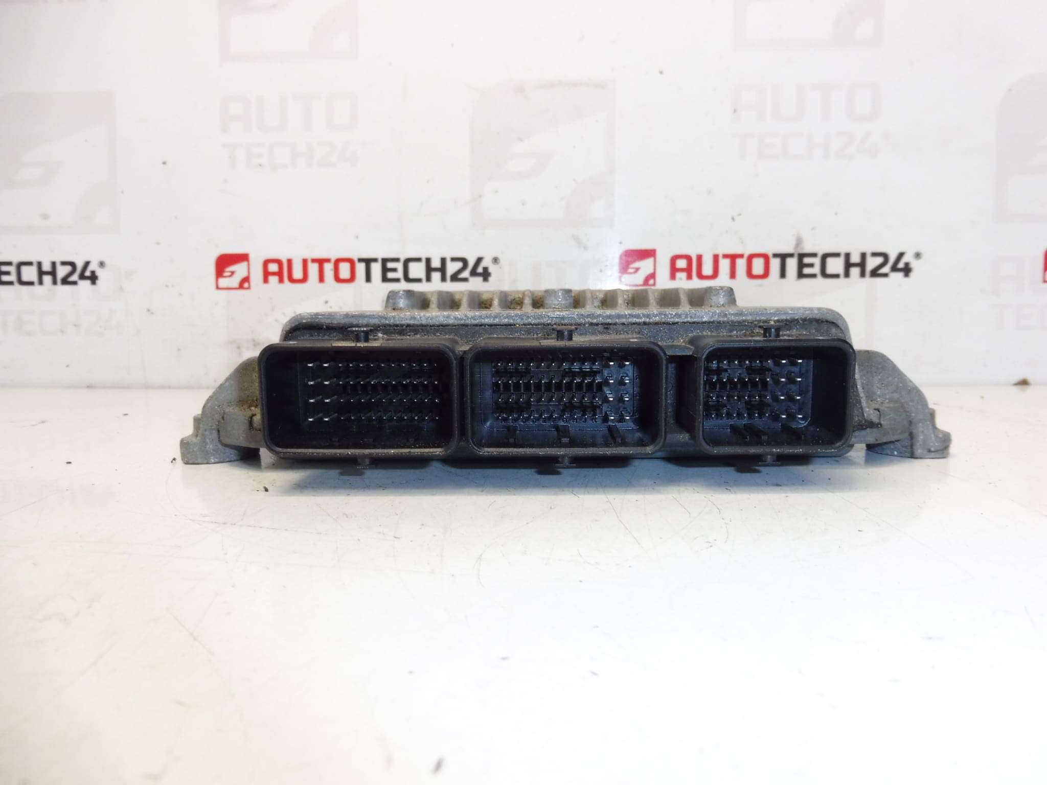
Injection Control Unit Continental SIEMENS SID 803A. It is from a 2010 Citroën C4 PICASSO 2.0 HDI RHE.
High-quality injection control unit (ECU) for PSA Group diesel engines, built on the Continental / Siemens SID803A platform. This unit is suitable for professional workshops and experienced DIY mechanics who service Citroën and Peugeot vehicles. Supplied with the common manufacturer codes used across PSA electrical systems, the module ensures accurate fuel metering, turbo control and emission management when properly programmed. Listing product codes in searches (5WS40690B-T, 9661642180, 9666095880, 1943QR, 1943QS) increases findability for technicians looking for exact replacements.
Technical Information
- Manufacturer: Continental (Siemens VDO)
- Model: Citroën C4 Picasso 2010 2.0 HDi (RHE)
- Product Codes: SID803A, 5WS40690B-T, 9661642180, 9666095880
- Additional Numbers: 1943QR, 1943QS
Key Features And Benefits
Engine management on this SID803A-based unit controls injection timing, rail pressure regulation and interacts with turbocharger and exhaust gas recirculation systems. For mechanics, the unit offers a direct drop-in electronic replacement when data is matched or cloned correctly, restoring engine performance and diagnostics compatibility. Using the correct part codes improves search engine visibility and speeds up replacement in busy workshops.
Installation And Coding – Important
- The unit is used and is “paired” with the original vehicle (VIN/PIN/keys).
- Options for commissioning:
- Cloning data from the old unit (EEPROM/Flash) – after cloning the unit is plug and play.
- Virginization and subsequent initialization/telecoding via DiagBox (or online) + key adaptation.
- Recommended to be carried out by a specialist with PSA service equipment (DiagBox/Lexia/PP2000).
- Always disconnect the battery before removal/installation and follow the manufacturer’s procedure to avoid damaging the unit.
Installation Recommendations
Before starting, isolate the vehicle battery and wait for any capacitors to discharge. Observe electrostatic discharge (ESD) precautions when handling the ECU. Locate the unit (position varies by model; refer to factory manual), unplug all connectors by releasing the locking mechanisms, remove mounting fasteners and extract the module. Fit the replacement in reverse order, ensure connectors are fully seated and locked, then proceed with cloning or coding as required. Do not attempt to power the module with incorrect wiring or without completing the coding/cloning step where necessary.
Why This Part Fails Most Often
Common causes of ECU failure include water ingress and corrosion at connector pins, voltage spikes or poor battery/charging system condition, thermal stress from engine compartment heating, and connector or harness damage during previous repairs. Symptoms often include engine running issues, loss of communication with diagnostic tools, limp-home mode or intermittent faults. In many cases, the electronic components themselves remain intact but configuration data is required to match the unit to the vehicle.
Practical Notes For Mechanics
When sourcing replacement ECUs, match the exact product codes and software labels rather than only the housing look. For a seamless repair: 1) Verify the part numbers stamped on the unit match the vehicle’s required codes, 2) Choose cloning if you need a quick plug-and-play solution, 3) Use official PSA diagnostic tools for virginization and key adaptation to ensure all vehicle subsystems accept the new module.
Suitability And Search Tips
Search engine visibility is maximized by using the ECU identifiers and vehicle model in keywords: SID803A, 5WS40690B-T, 9661642180, 9666095880, 1943QR, 1943QS, Citroën C4 Picasso, 2.0 HDi, RHE. These identifiers help mechanics and parts managers find an exact match quickly.