Description
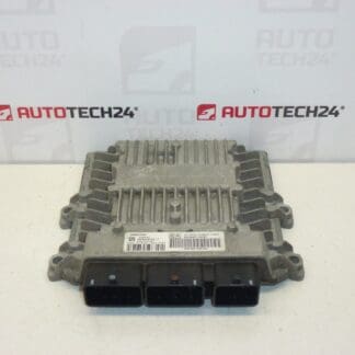
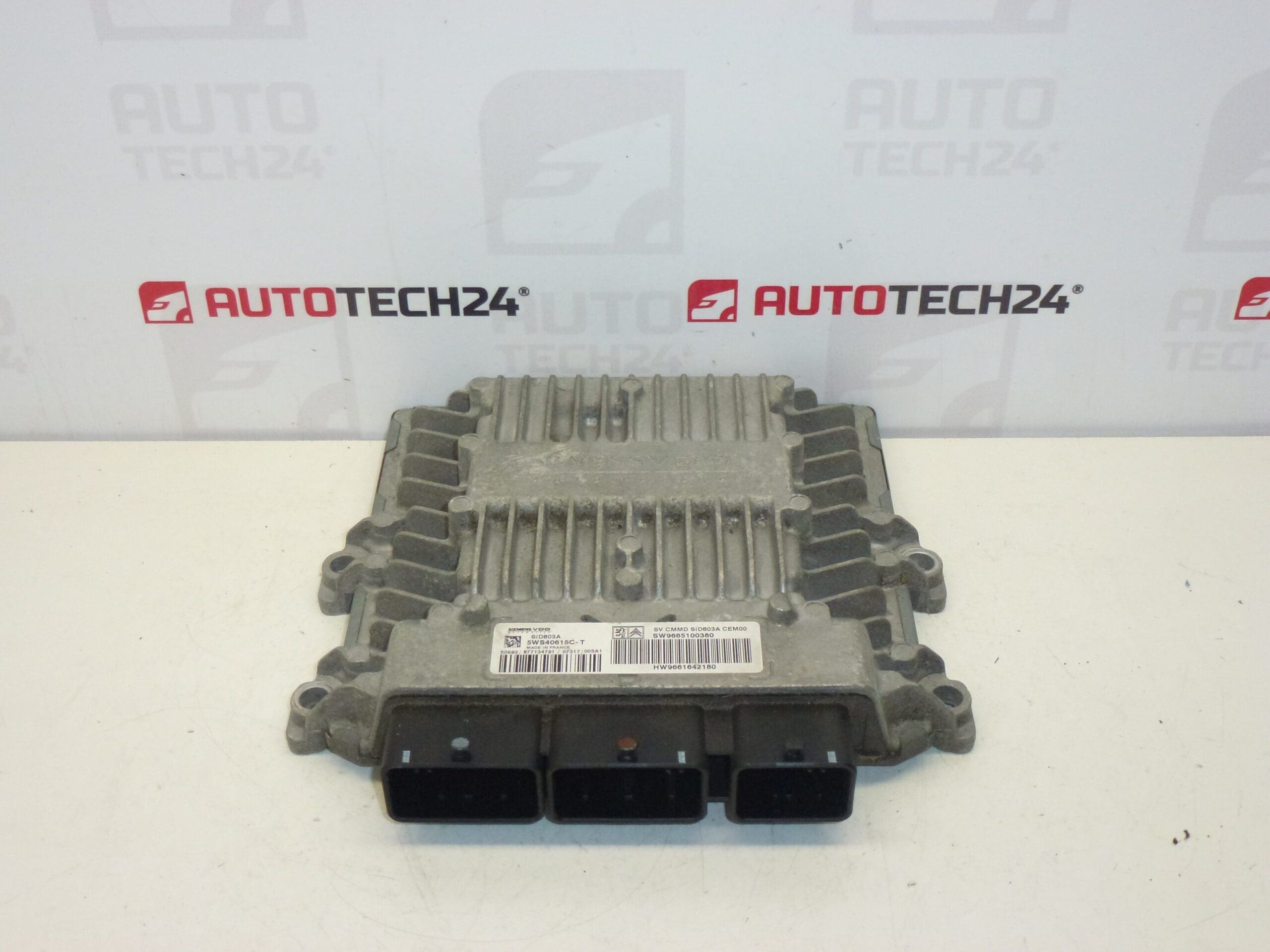
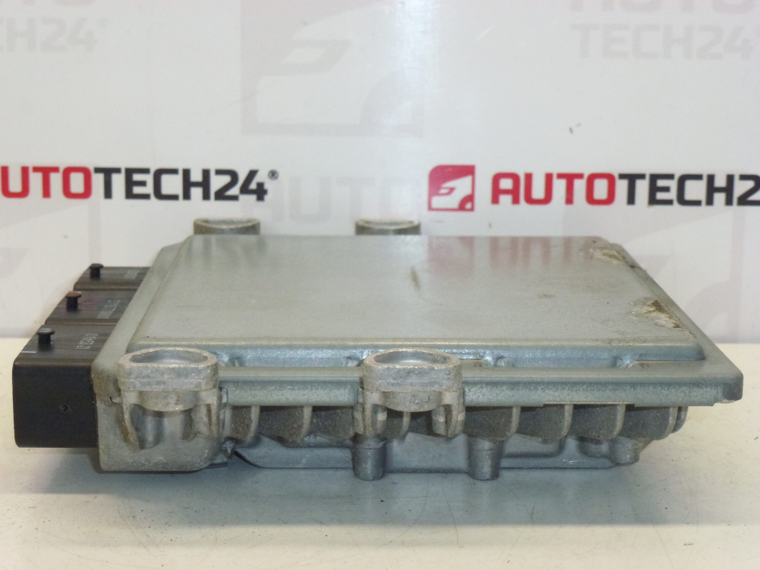
Injection control unit Continental SIEMENS SID 803A
It is from a 2008 CITROEN C4 GRAND PICASSO
Part description
This injection control unit is an original used car part designed for Citroën and Peugeot cars within the Stellantis concern. It is a Siemens VDO / Continental SID803A unit, which is often searched for by serial numbers and codes on the label. For auto mechanics and home repairers, the exact identification of the unit is particularly important, because the matching of the codes is crucial when replacing them.
The part comes from a Citroën C4 Grand Picasso and can be a suitable solution in the event of a failure of the original ECU, unstable engine operation or a replacement for a damaged unit. For used control units, the key is to compare all markings on the original and spare part.
Technical information
- Manufacturer: Continental SIEMENS
- Model: SID 803A
- Other numbers: 5WS40615C-T, 9661642180, 9665100380, 1943JK, 1943JL, 1677622480
Product codes
- Product codes: 5WS40615C-T, 9661642180, 9665100380, 1943JK, 1943JL, 1677622480
- Model names: Citroën C4 PICASSO, Citroën C4 GRAND PICASSO
Installation recommendations
This item is an injection control unit. The exact replacement procedure may vary by vehicle, but below is a safe and practical procedure typically used for this type of part.
1) Before assembly
- Check that all numbers and markings on the original and replacement units match.
- Compare the connectors, their number, shape and overall appearance of the unit.
- Inspect the used part for damaged packaging, connectors, pins, handles or traces of moisture.
- Before disassembling the original unit, it is advisable to check the condition of the wiring and connectors so that the fault is not caused by another part of the electrical installation.
2) Necessary tools and materials
- Basic set of hand tools
- Suitable bits or heads according to the type of fastening
- Cleaning agent for electrical connectors
- Protective gloves
- Diagnostic equipment for subsequent adjustment or function check
3) Step-by-step assembly procedure
- Turn off the ignition and leave the vehicle in idle mode.
- Disconnect the battery according to the usual principles of safe work on the electrical system.
- Access the original control unit according to the vehicle design.
- Carefully disconnect all electrical connectors without prying or twisting.
- Unmount the original unit and remove it from the vehicle.
- Compare the old and replacement part including all labels, connectors and attachment points.
- If necessary, gently clean the connectors and check that they are not oxidized or mechanically damaged.
- Place the replacement unit in place and secure it properly.
- Connect the connectors so that they are fully seated and properly secured.
- Reconnect the battery.
- Perform the necessary diagnostic actions according to the unit type and vehicle equipment.
- After installation, verify the basic function of the system and check whether there are any malfunctions.
-
4) Post-assembly checks and test drive/function verification
- Check that all connectors are properly secured.
- Verify unit communication with diagnostics.
- Monitor for non-standard operating behavior.
- After a successful start-up, perform a short verification of the vehicle’s function in normal operation.
- After checking, recheck that the unit is firmly seated and there is no tension in the wiring.
5) The most common assembly mistakes + how to avoid them
- Unit swapping based on incomplete designation – always compare all numbers on the label.
- Assembly with a damaged connector – check the pins and latches of the connectors before connecting.
- Connecting with the battery connected – always work with the battery disconnected.
- Overlooking a fault in the wiring – if the cause was a fault in the electrical installation, replacing the unit alone will not solve the problem.
- Insufficient mounting – the unit must be properly seated and secured against vibration.
Assembly and Coding – Important
– The unit is used and is “paired” to the original car (VIN/PIN/keys).
– Activation options:
1) Cloning data from the old drive (EEPROM/Flash) – after the clone, the drive is plug and play.
2) Virginization and subsequent initialization/telecoding via DiagBox (possibly online) + customization of keys.
– Recommended to be performed by an expert with PSA service equipment (DiagBox/Lexia/PP2000).
– Always disconnect the battery before disassembly/assembly and follow the manufacturer’s procedure to avoid damaging the unit.Reasons why the part is damaged
- Voltage fluctuations in the on-board network or power supply problems
- Moisture, oxidation of connectors or ingress of dirt
- Cabling damage, short circuit or transition resistances in the connectors
- Mechanical stress, vibration or unprofessional handling during disassembly
- Damage caused during starting, charging or tampering with the vehicle’s electrical installation