Description
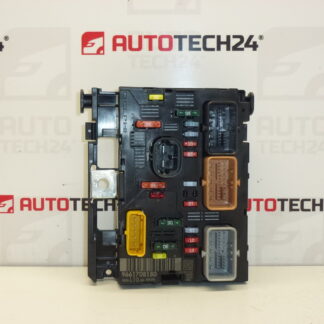
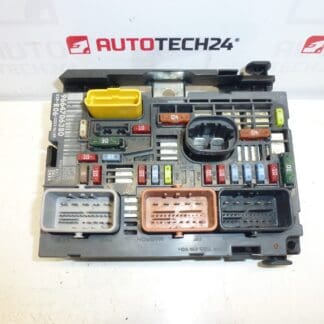
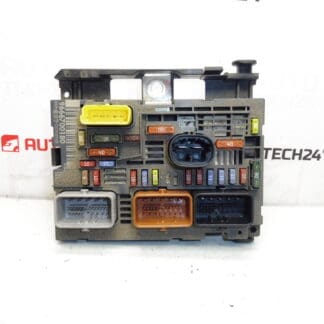
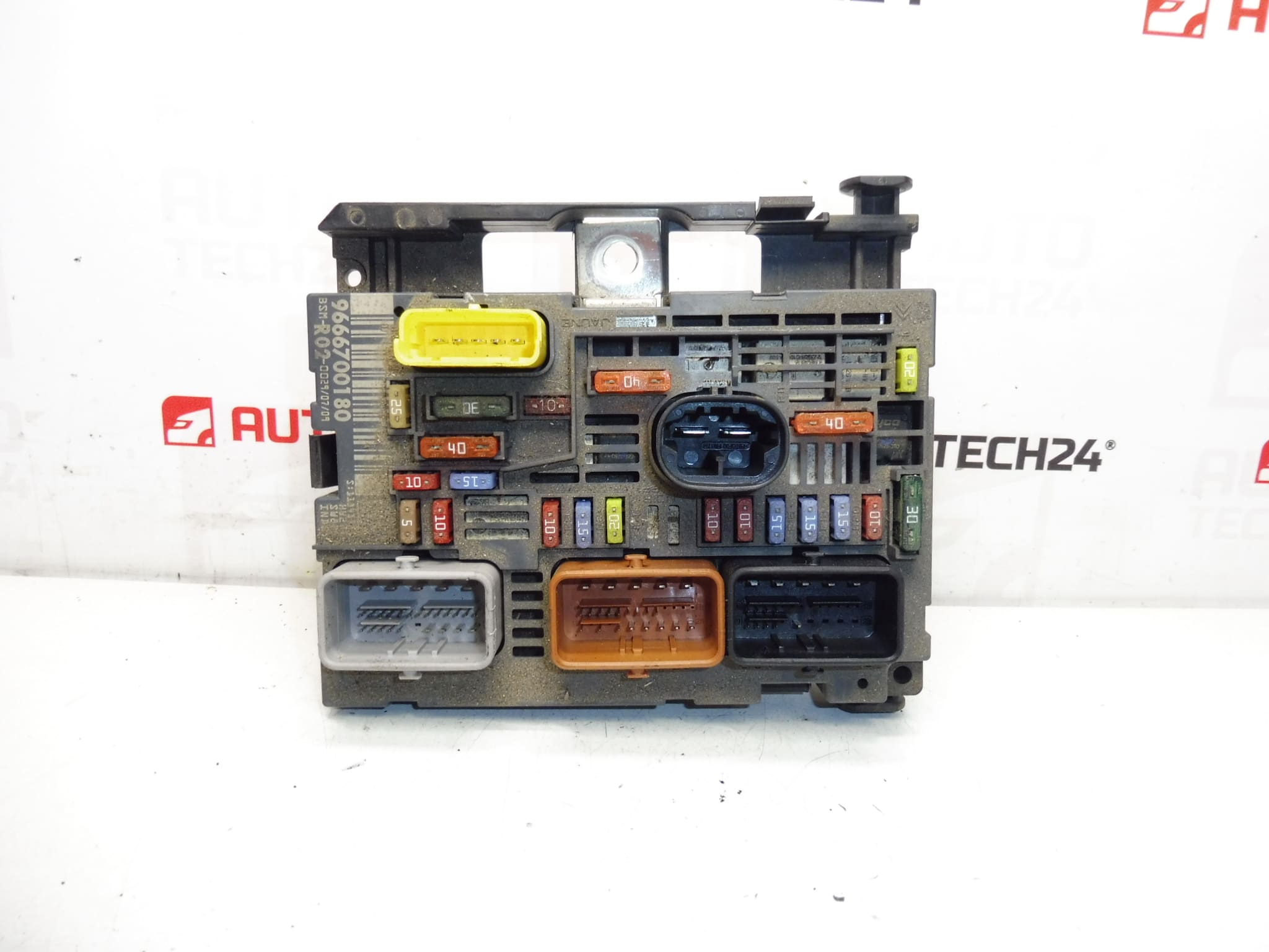
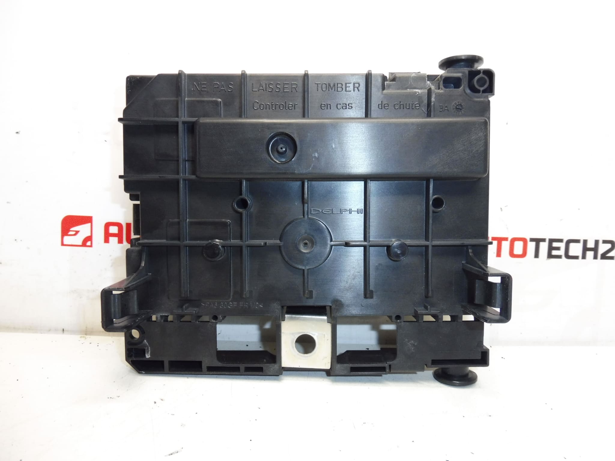
BSM DELPHI R02-00 for CITROEN PEUGEOT cars
One of the holders on the package may be cracked, which does not affect the function
The unit is fully functional
Part description
This BSM unit Siemens R02-00 is intended for Citroën and Peugeot cars and is mainly searched by original part numbers. It is an important electrical component of the engine unit, which is used as a spare part in the event of a failure of the original module or when solving problems in the vehicle’s electrical installation.
The advantage is that it is a fully functional used car part. The package may have a cracked holder, which does not affect the unit’s function according to available information. It is a practical choice for auto mechanics and DIYers when repairing a car when it is necessary to maintain the correct markings and matching codes.
BSM is often searched for by a specific designation, so we recommend paying attention to all listed numbers and labels.
Technical information
Part category: BSM – motor unit / electrical components / control unit.
Product codes
- Product codes: 9666700180, 9807028580, 6500FQ, 6500HK
- Models from labels: 5008 I, Citroën C4 PICASSO, Citroen C5 X7, Peugeot 407
Installation recommendations
This part is a BSM unit. The exact assembly steps may vary according to the specific model and design of the car, so below we present a generally valid procedure typically for replacing this type of electrical part.
1) Before assembly
- Check that R02-00 and all important part numbers match.
- Compare the connectors, pin arrangement, fuse and relay placement and package shape with the old piece.
- Check the condition of the contacts, whether they are oxidized, loose or mechanically damaged.
- Verify the condition of the drive cabinet. A cracked holder on the package may not affect the function, but it is advisable to check whether the part will be able to be securely fixed.
- Before starting work, disconnect the battery and wait for the car’s electrical system to calm down.
2) Necessary tools and materials
- Basic set of hand tools
- Appropriate tools for releasing covers and connectors
- Cleaning agent for electrical contacts
- Protective gloves and possibly a flashlight
3) Step-by-step assembly procedure
- Secure the vehicle against movement and turn off the ignition.
- Disconnect the battery according to normal safe procedure for working on vehicle wiring.
- Access the space where the original BSM unit is mounted.
- Carefully document the connection of the connectors and the possible layout of the connected elements so that there is no confusion during assembly.
- Carefully disconnect all connectors. Do not use excessive force and release the connector locks in the correct direction.
- Remove the original unit from the brackets or mounts.
- Compare the old and new part side by side again, especially the numbers, connectors and design.
- If necessary, gently clean the contact surfaces and check the connectors for dirt or signs of overheating.
- Place the replacement BSM unit in place and secure it properly.
- Plug all the connectors back in the correct order and check they are fully seated.
- Reinstall all covers and parts that had to be removed for access.
- Reconnect the battery and perform a basic check of power and related electrical circuit functionality.
-
4) Post-assembly checks and test drive/function verification
- Check for unusual behavior in the power supply to the electrical systems when the ignition is turned on.
- Verify the correct operation of circuits that are normally powered or switched via the BSM.
- After starting, observe the stability of the vehicle operation and any warning messages.
- Do a short test drive and then double check that the unit is firmly seated and the connectors hold without play.
5) The most common assembly mistakes + how to avoid them
- Part exchange by incomplete number – always compare all available designations.
- Connector damage during disassembly – release the connectors carefully and never pull them out by force.
- Mounting on dirty or oxidized contacts – check the contacts before installation and clean them if necessary.
- Insufficient fixing of the unit – although a cracked packaging holder may not affect function, the part must be firmly seated after assembly.
- Working under voltage – always disconnect the battery before handling the unit.
Reasons why the part is damaged
- long-term load on wiring and age of components
- moisture, oxidation of contacts and ingress of dirt
- voltage fluctuations in the on-board network
- overheating or local damage to contacts and connectors
- mechanical damage during disassembly, assembly or handling