Description
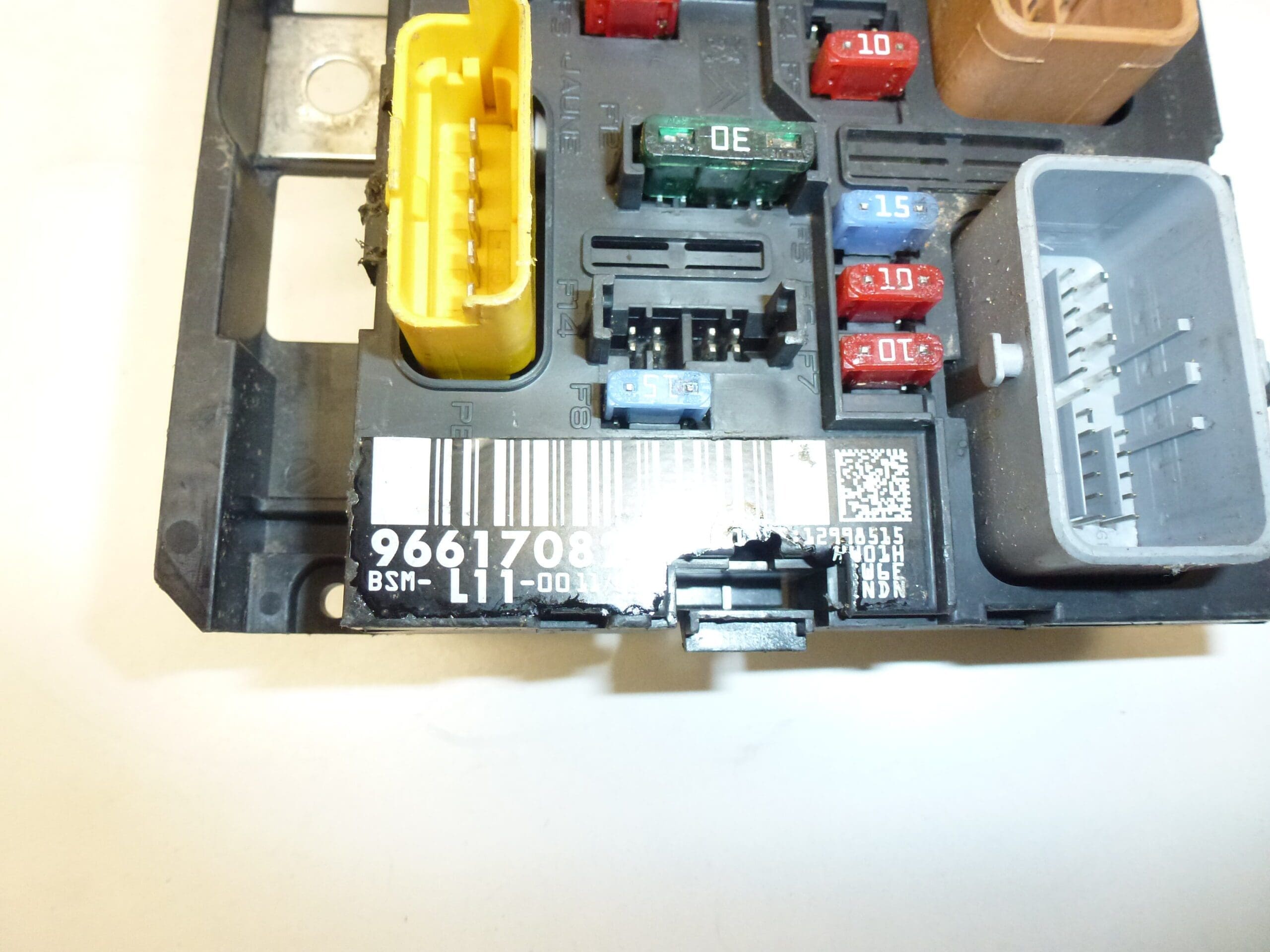
BSM L11-00 DELPHI for Citroën and Peugeot
Part description
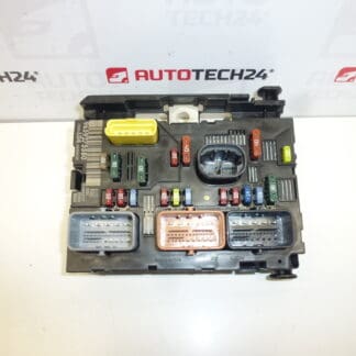
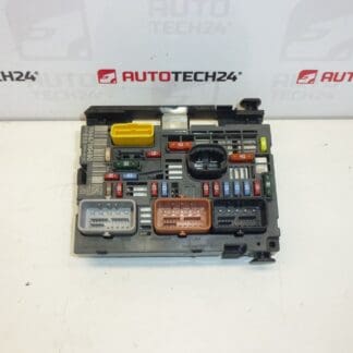
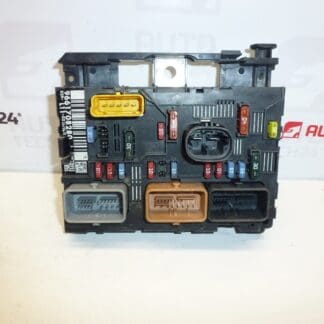
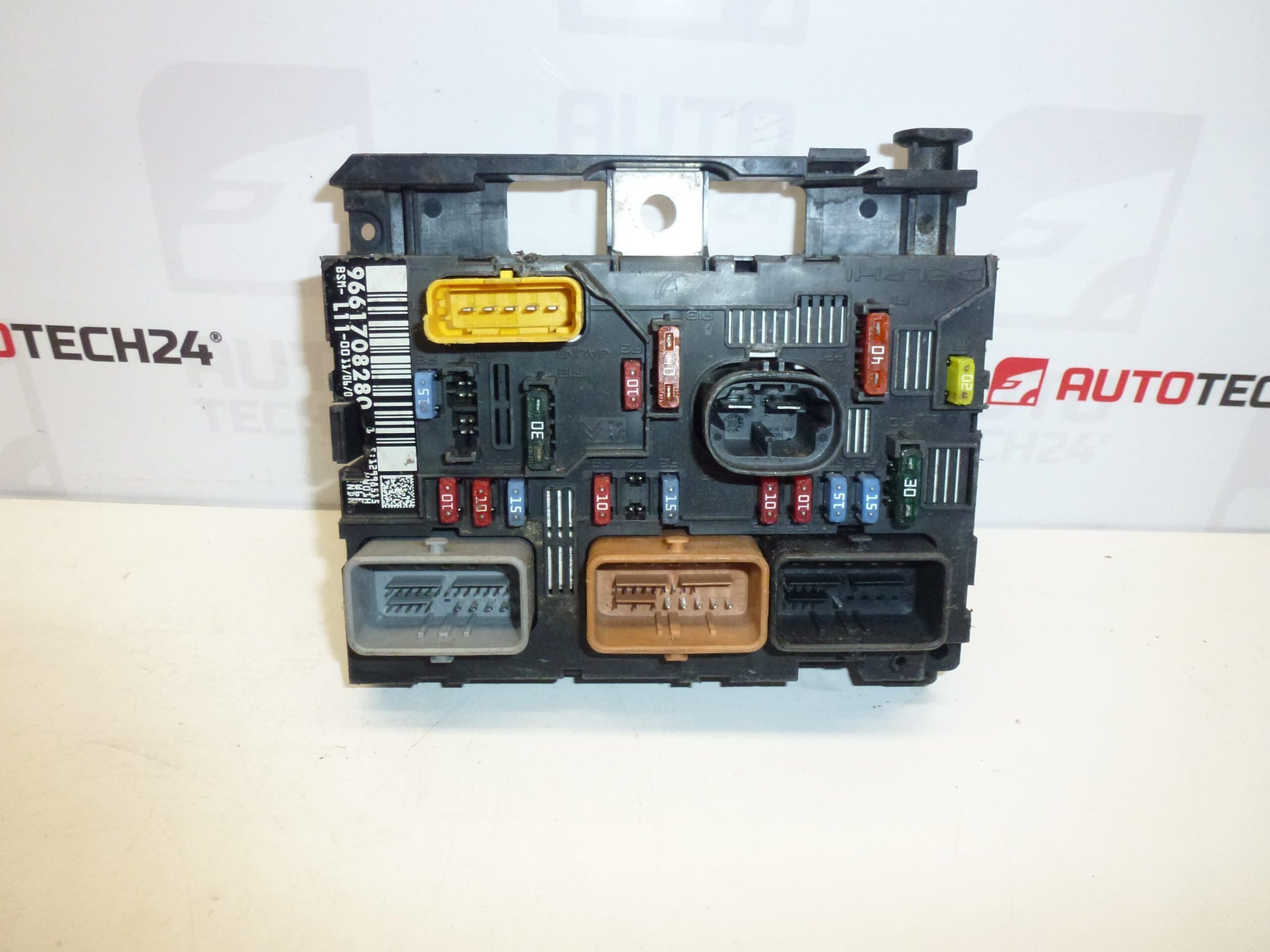
BSM L11-00 DELPHI 9661708280 is a used electrical module for Citroën and Peugeot cars. The BSM generally serves as a fuse and switching module, which ensures power distribution and switching of selected electrical circuits of the vehicle. It is not a BSI unit or an injection control unit.
The documents include the models Peugeot 207 and Peugeot 307. When choosing a spare part, compare the product number, the designation L11-00 and the design of the connectors with the original module. The model name alone is not enough to choose the right variant. A used original part can be a cost-effective repair solution if diagnostics have confirmed a defect in the original BSM.
Technical information
- Manufacturer: DELPHI
- Model: Peugeot 207, Peugeot 307
- Part Type: BSM – Fuse and Switch Module
- Designation: L11-00
- Main Product Number: 9661708280
- Other numbers: 6500CK, 6500FH
- Other designations in the documents: NFP
- Condition: used part
- Specific years and engines: not specified
Product codes
Product codes: 9661708280, 6500CK, 6500FH.
Variant designation: BSM L11-00 DELPHI. The given codes make it easy to locate the part; their assignment to a specific car design must be assessed together with the designation of the original module and service documentation.
Installation recommendations
The following procedure is general for replacing the BSM module. The exact steps, access to the part, and the procedure for disconnecting and reconnecting the battery depend on the specific model and make of the car. Follow the manufacturer’s service documentation.
1) Before assembly
- Verify with diagnostics that the cause of the fault is indeed the BSM and not a fuse, wiring, faulty power supply, grounding or connected appliance.
- Compare the numbers and markings of both modules, the shape of the case, the attachment, the number of connectors and their mechanical keying.
- Inspect the used part: check for cracks, damaged latches, bent contacts, corrosion, traces of moisture and overheating.
- Also check the car’s connectors and wiring. A damaged counterpart can cause a malfunction even after the module has been replaced.
2) Necessary tools and materials
- Common hand tools suitable for fixing the part and battery clamps.
- Tool for gentle release of plastic latches, flashlight and means for marking connectors.
- A multimeter and possibly a diagnostic device suitable for the car.
- A clean dry cloth, or a means for cleaning electrical contacts.
3) Step-by-step assembly procedure
- Stop the vehicle safely, secure it against movement and switch off electrical appliances and the ignition.
- Let the electronics go to sleep according to the manufacturer’s procedure. Then disconnect the battery as prescribed; do not disconnect the BSM connectors under voltage.
- Access the module according to the service procedure of the specific car. Loosen the covers and plastic handles without force.
- Take a photo of the wiring and label the connectors to avoid confusion during assembly.
- Release the connectors’ fuses and disconnect the connectors by their bodies. Do not pull on the wires.
- Unfasten the original module and carefully remove it.
- Inspect the storage space, connectors and leads. Eliminate the cause of any leaks or damage to the wiring before proceeding.
- Compare both modules again. Assess the installation of fuses according to the documentation of the specific car; don’t move them or change their values blindly.
- Place the replacement BSM in the holder and fasten it in the prescribed manner. The wiring must not be stretched or pinched.
- Connect the connectors and close their securing. Verify full seating without applying excessive force.
- Install the protective covers, check the wiring and connect the battery according to the manufacturer’s procedure.
- Perform the prescribed restoration of the operation of the electrical system and subsequent function check, possibly diagnosis.
-
4) Post-assembly checks and test drive / function verification
Verify the starting and operation of the electrical circuits related to the original fault. Check for power outages, overheating odors, or abnormally hot connectors. If diagnostics are available, compare the condition before and after the repair. Carry out a short test drive only after a successful on-site inspection and then verify that the original defect does not return.
5) The most common assembly mistakes and how to avoid them
- Choose only by car model: also compare product numbers, module variant and connector design.
- Disconnecting under voltage: always follow the procedure of putting the electronics to sleep and disconnecting the battery.
- Unfinished connectors: check their seating and securing, not just the visually connected position.
- Leaving damaged wiring or contacts: eliminate related defects before putting the replacement module into service.
- Incorrect fuses or fuse bypass: use only the equipment prescribed for the specific car.
- Moisture and corrosion – disrupt contacts and can cause irregular outages of electrical circuits.
- Transient resistance in connectors – loose or oxidized connections heat up and can damage contacts and housing.
- Short circuit or overload of the connected circuit – defective wiring or appliance can stress the switching and power parts of the module.
- Incorrect interventions in the electrical installation – inappropriate securing, unprofessional modifications or improper handling of the power supply increase the risk of damage.
- Aging and thermal stress – can gradually affect internal connections and switching elements.
- Mechanical damage during disassembly – forcefully releasing connectors can damage latches, contacts or module body.
Reasons why the part is damaged
For BSM modules in general, the following influences can lead to damage; it is not a description of the detected condition of this piece: