Description
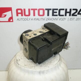
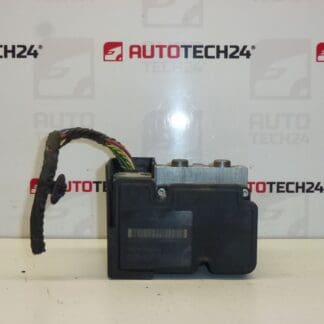
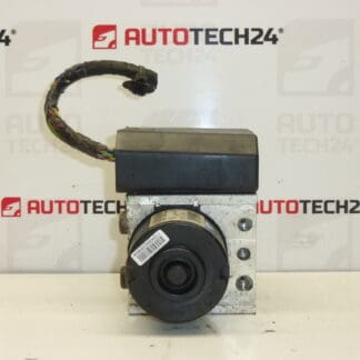
Control module, ABS pump, ABS cube ATE CITROEN C3, C3 II also fits PEUGEOT 207
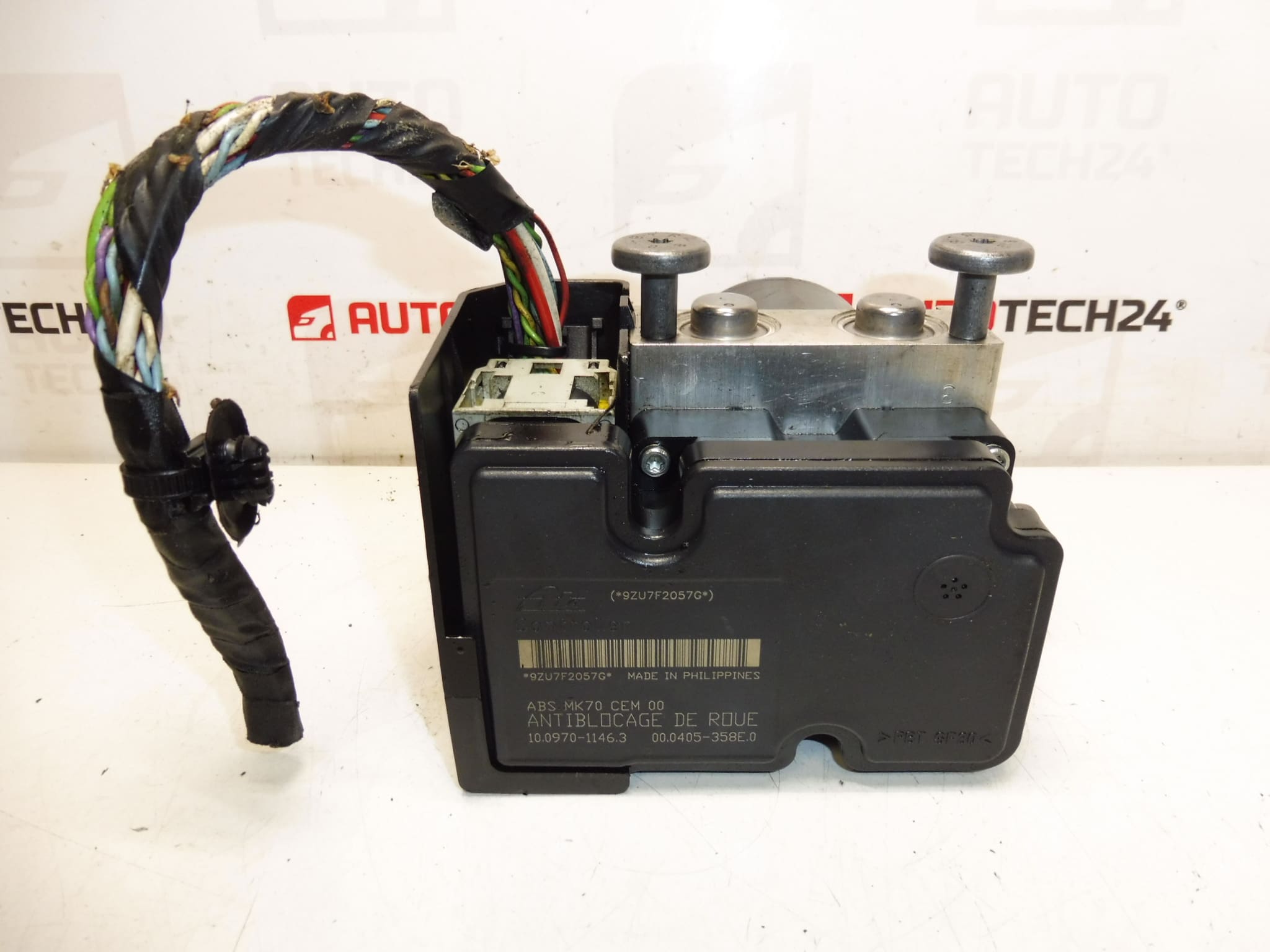
Hydraulic brake control block
With a piece of wiring
Part description
This part is an ABS ATE module (control module with hydraulic block/pump), intended for the brake system of the Citroën C3, C3 II and, as indicated, also the Peugeot 207. The ABS unit takes care of controlling the pressure in the brakes during emergency braking and helps maintain the car’s controllability.
A piece of wiring is included, making it easy to connect and check the connectors when changing. Parts of this type are often searched by number – so we list all known codes below.
Technical information
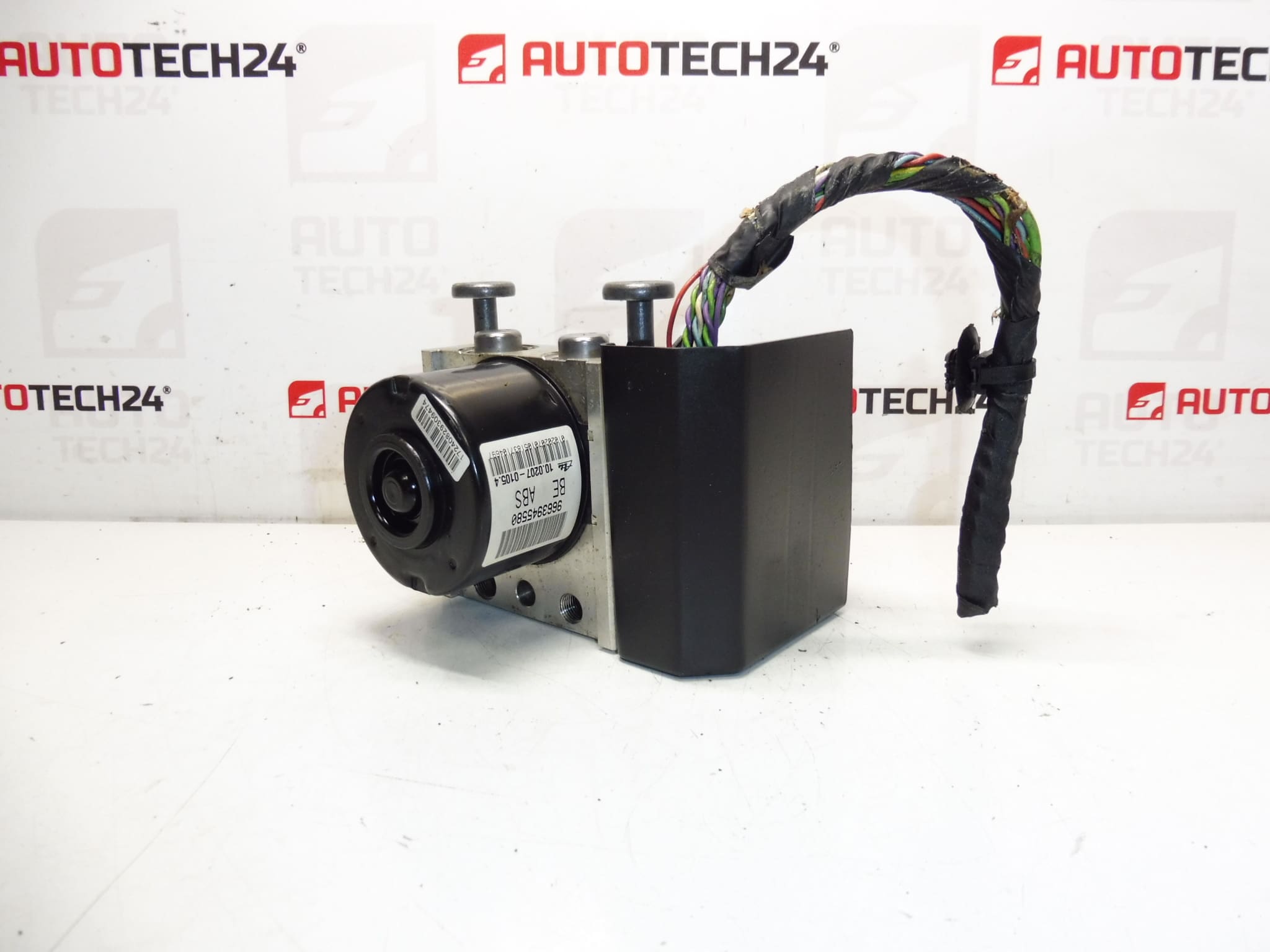
- Manufacturer: ATE
- Model: Citroën C3, Citroën C3 II, Peugeot 207
- Other numbers: 4541FY, 4541FX, 1682607180, 4542N2, 4542N1, NFP
Product codes
- Product codes: 9663945580, 10.0207-0105.4, 10.0970-1146.3, 4541FY, 4541FX, 1682607180, 4542N2, 4542N1, NFP
Installation recommendations
Generally/typically, replacing the ABS module/pump with the hydraulic block is an intervention in the braking system. The exact procedure may vary depending on the specific car design and equipment.
1) Before assembly
- Compare with the old part: all numbers on the label (eg 9663945580, 10.0207-0105.4), type of connectors and their fuses.
- Check the condition of the connectors and the attached piece of wiring (undamaged pins, no corrosion, no torn insulation).
- Visually check the hydraulic block body and threads/brake lines (no cracks or deformations).
- Prepare a clean working environment in advance – dirt in the system causes problems with brakes.
2) Necessary tools and materials
- Normal set of gola/ratchets and bits, screwdrivers
- Wrenches for brake pipes (to minimize screwing off)
- Brake line plugs/seals (to limit fluid leakage and dirt ingress)
- Cleaning agent for electrical contacts, rags
- Suitable equipment for bleeding the brakes (according to your practice and possibilities)
3) Step-by-step assembly procedure
- Secure the vehicle against movement and disconnect the battery.
- Locate the ABS unit and access it by removing the obstructing covers (depending on the model of the car).
- Mark the brake lines (e.g. with tape) to avoid confusion during reassembly.
- Disconnect the unit’s electrical connectors (including any wiring) and check the locking mechanisms.
- Carefully loosen the brake fittings/lines; continuously plug open ends to prevent dirt from entering the system.
- Unfasten the drive and remove the old module.
- Install the new used ABS module in the holder and tighten the fastening (without changing the threads).
- Screw the brake lines back in – first by hand so the threads don’t cross, then tighten with a suitable wrench.
- Connect the electrical connectors; make sure the contacts are clean and the fuses are properly engaged.
- Refit the dismantled covers/parts in the engine compartment (depending on the car).
- Bleed the brake system according to the normal procedure for the car and check the brake fluid level.
-
4) Post-assembly checks and test drive/function verification
- Check the tightness of all brake line connections (dry connections, no leaks).
- Verify firm operation of the brake pedal and basic operation of the brakes at low speed in a safe place.
- If you have a diagnostic, perform an ABS/ESP system check and verify that there are no associated fault reports.
5) The most common assembly mistakes + how to avoid them
- Replacing brake lines → always mark them before dismantling.
- Broken brake pipe fittings → use brake pipe wrenches and loosen with sensitivity.
- Impurity in the brake system → blind, keep clean, leave the line open for as short a time as possible.
- Poorly engaged connector / pin corrosion → visual inspection, contact cleaning, connector fuse check.
- Insufficient venting → follow best practice for the car and check pedal operation after venting.
Reasons why the part is damaged
- Moisture and corrosion of connectors (increased transition resistance, communication failures).
- Electronic aging and temperature stress in the engine compartment (cracked connections, unstable function).
- Brake fluid contamination and internal clogging of the hydraulic block.
- Mechanical damage (impact, unprofessional handling during brake repair).
- Electrical overvoltage or bad grounding in the vehicle installation.