Description
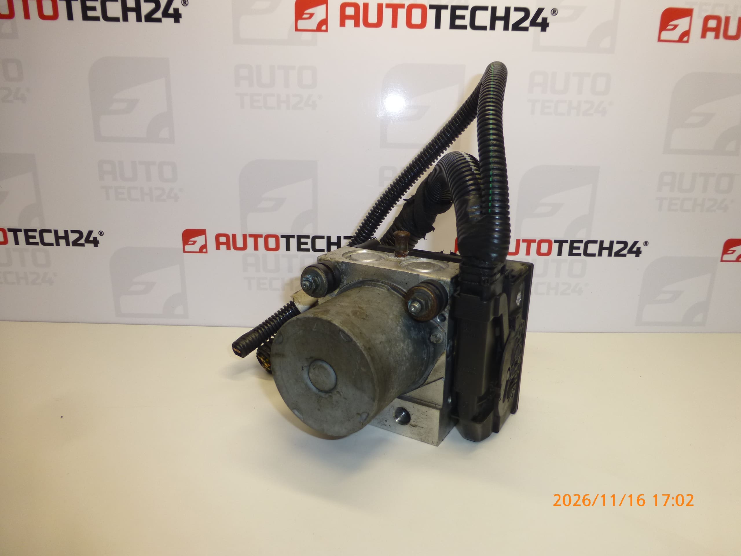
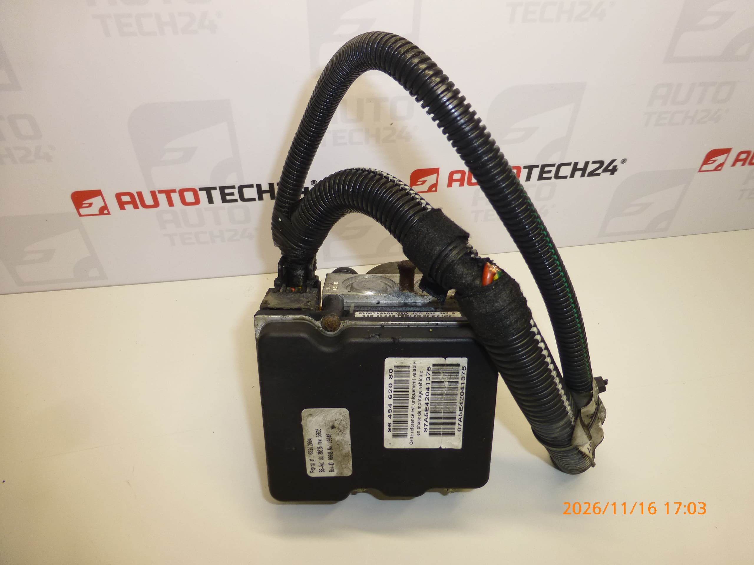
Control module, ABS pump, ESP unit, BOSCH ABS unit for CITROËN C4 vehicles
ABS brake control hydraulic block
With a piece of wiring
Part description
Used Bosch ABS/ESP module for Citroën C4 combines the control unit with the pump and the brake control hydraulic block. The ABS system helps limit wheel lockup during braking, while ESP supports vehicle stability by applying the brakes. Correct operation of the unit is therefore important for safe vehicle operation.
The part is suitable as a replacement when a fault in the corresponding unit has been confirmed. The markings 9649462080, 0265950370 and 4541E4, together with the design of the original part, are essential when selecting a replacement. A piece of wiring is included; this is not stated to be a complete wiring harness. This used part offers a repair option without purchasing a new unit; however, before replacement, it is important to rule out a fault in the power supply, wiring, or other system components.
Technical information
- Manufacturer: Bosch
- Model: Citroën C4
- Part type: ABS/ESP control module, pump and brake control hydraulic block
- Condition: used automotive part
- Included according to the information provided: piece of wiring
- Additional numbers: not specified
- Additional marking in the information provided: NFP
- Model years and engine variants: not specified
Product codes
- Product codes: 9649462080, 0265950370, 4541E4
- Model: Citroën C4
When selecting a part, compare the codes listed with the markings on the original unit and the requirements in the service documentation for the specific vehicle configuration. A matching model name alone is not sufficient grounds for substituting ABS/ESP units.
Installation recommendations
The following procedure is a general guide to replacing an ABS/ESP hydraulic unit. The exact method of removal, bleeding, and any required adjustment depends on the specific model and vehicle configuration. This work involves the braking system, so have it carried out by a technician with the appropriate knowledge, equipment, and access to the manufacturer’s service procedures.
1) Before installation
- Use diagnostics to verify the cause of the fault. An ABS/ESP warning light by itself does not confirm damage to the hydraulic unit.
- Compare the markings, connectors, mounting points, and arrangement of the hydraulic connections with the old part.
- Inspect the body of the used part, threads, electrical contacts, and the included piece of wiring. Look for cracks, corrosion, damaged insulation, and signs of leaks.
- Check that the hydraulic ports are clean. If internal contamination or damage is suspected, do not install the part without a professional assessment.
2) Tools and materials required
- Standard installation tools and suitable wrenches for brake pipe fittings.
- A torque wrench for tightening to the manufacturer’s service specifications.
- Diagnostic equipment that supports the relevant ABS/ESP system and its service functions.
- Brake bleeding equipment, clean protective caps, a collection container, and supplies for safely cleaning the area around the connections.
- Brake fluid that meets the vehicle manufacturer’s specification, protective gloves, and safety glasses.
3) Step-by-step installation procedure
- Secure the vehicle against movement and prepare a clean work area. If lifting and supporting the vehicle is necessary, do so in accordance with service procedures.
- Before disconnecting the unit, read and record the diagnostic faults and any available configuration data for the original system.
- Switch off the ignition and disconnect the battery according to the manufacturer’s procedure. Observe the specified waiting times and any system depressurization procedure.
- Access the unit according to the service documentation. Thoroughly clean the area around the hydraulic connections and connectors before disconnecting them.
- Document the routing and label each brake pipe so that they cannot be mixed up during installation.
- Release the connector locks and disconnect the electrical connection without pulling on the wires. Do not connect the included piece of wiring based solely on wire colors; any harness repair must be carried out according to the wiring diagram.
- Carefully disconnect the brake lines, catch any escaping fluid, and immediately protect the open ends with clean caps. Prevent dirt from entering and avoid unnecessarily draining the system.
- Release the mounting points and remove the original unit. Fit the replacement part without applying strain and secure it according to the service specifications.
- Connect the hydraulic lines to the correct ports. Start the threads by hand, tighten the connections to the specified values, and then secure the electrical connectors.
- Restore the power supply according to the manufacturer’s procedure and carry out the prescribed fluid top-up and bleeding. If the service procedure requires diagnostic activation of the ABS pump and valves, use the appropriate service function.
- Use diagnostics to verify communication with the unit and, as required for the specific vehicle, perform any necessary configuration, initialization, or calibration. Before finishing, check all disconnected connections for leaks.
4) Post-installation checks and function verification
Check the fluid level, connection tightness, stable brake pedal resistance, and warning lights. Run diagnostics again and verify that no relevant faults recur. Do not operate the vehicle if the pedal is soft or sinks, there is a fluid leak, or a brake fault remains unresolved. Carry out a test drive only after the static checks have been completed successfully, starting at low speed in a safe environment. ABS/ESP intervention testing must be performed under controlled conditions, not in normal traffic.
5) Common installation errors and how to avoid them
- Replacing the unit without diagnostics: first rule out faults in the power supply, contacts, wiring, and sensors.
- Mixing up the hydraulic lines: label them and record their connections before removal.
- Contamination in the hydraulics: keep the work area clean and do not leave open connections unprotected.
- Damaging threads or pipes: start fittings by hand, use suitable tools, and do not connect lines under strain.
- Insufficient bleeding: follow the entire prescribed procedure, including diagnostic functions if required.
- Skipping unit setup: check the requirements for the specific configuration; do not assume the unit will work immediately after connection.
Reasons why the part may become damaged
In general, the following factors can cause damage to ABS/ESP units. This is not a description of the confirmed condition of this specific part.
- Moisture and corrosion in connectors, wiring, or the electronic component.
- Electrical overload and improper work on the power supply, which can damage the control electronics.
- Wear of the pump and internal components through prolonged use.
- Contaminated or neglected brake fluid, which can contribute to corrosion and hydraulic valve failures.
- Mechanical damage caused by an accident, improper removal, or forceful connection of lines and connectors.
- Contamination introduced during repairs, which can impair the correct operation of the hydraulic block.