Description
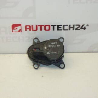
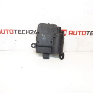
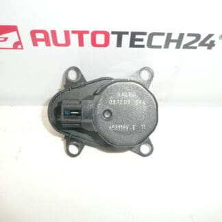
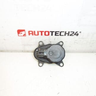
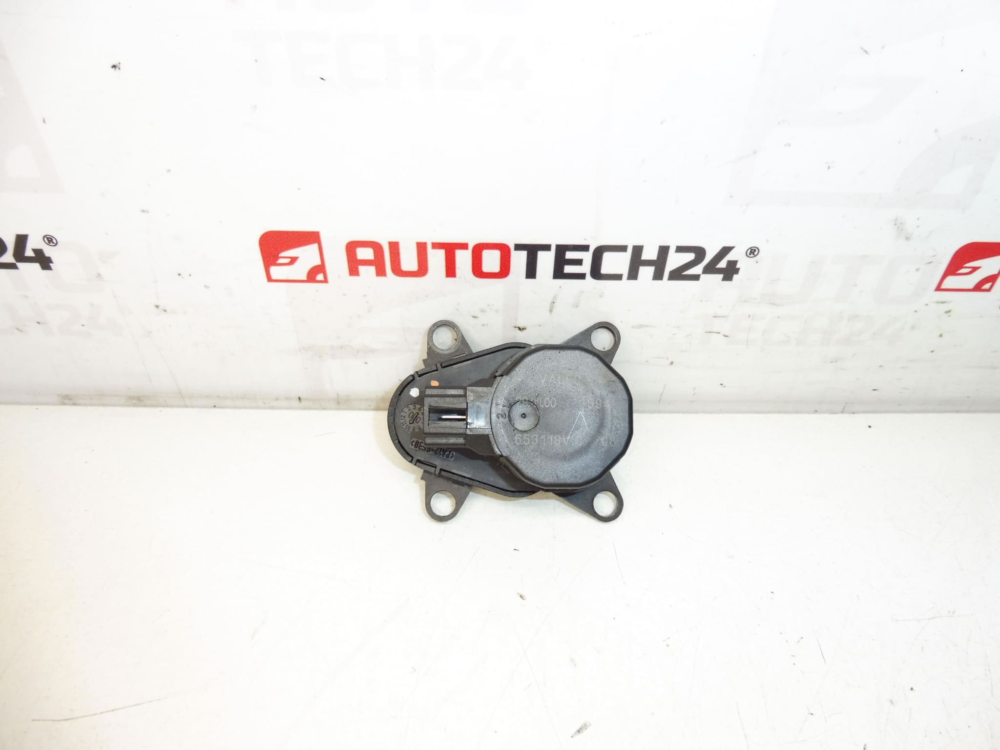
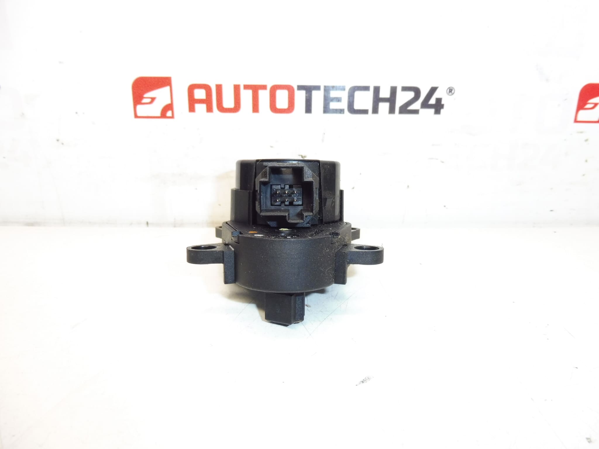
VALEO heater servo motor for CITROEN and PEUGEOT cars
It is possible that we will send a full original VALEO replacement
Part description
This heating servo motor is designed for Citroën and Peugeot cars and serves as an electrical part of the heating and ventilation system. It is a used car part suitable for repairs in which it is important to maintain the correct function of the control of the heating flaps.
The part is associated with the VALEO brand, which is commonly used in original production and as an original replacement. Thanks to the specified product numbers, the servo motor is easy to find when searching by code, which will be appreciated by both car repair shops and home mechanics when replacing a non-functional part.
According to the available documents, this part appears in the Citroën C5 I, Peugeot 406, Peugeot 607 and Citroën Xsara models.
Technical information
- Manufacturer: VALEO
- Model: Citroën C5 I, Peugeot 406, Peugeot 607, Citroën Xsara
- Other numbers: 653118V.E 11, 653118V.C 09, 653118V.C 08, 653118V.C 06, 653118V.C 05, 6447HH
Product codes
Product codes: 653118V.C 06, 6447HH, 653118V.E 11, 653118V.C 09, 653118V.C 08, 653118V.C 05
Installation recommendations
Generally/typically, the exact replacement procedure for the heater servo motor depends on the specific car model and the type of heating or air conditioning. Below is a practical general procedure for replacing this type of electrical part.
1) Before assembly
- Check that the part codes and connector match the old part.
- Compare the shape of the motor body, the attachment, the position of the mounting holes and the design of the output shaft or gear.
- Inspect the condition of the used part – especially the connector, plastic latches, teeth and any signs of damage or excessive wear.
- Before disassembling the original part, it is advisable to take a photo of the location and routing of the cabling.
2) Necessary tools and materials
- A common set of hand tools
- Screwdrivers or bits corresponding to the type of fastener
- Small ratchet and extension for working in limited space
- Plastic pry bar for removing covers
- Flashlight or workshop lighting
- Clean cloth for cleaning around the part and the connector
3) Step-by-step assembly procedure
- Turn off the ignition and secure the vehicle against movement.
- Disconnect the battery, especially if you will be working near electrical components of the interior.
- Remove the necessary covers or trim to gain access to the heater servo motor.
- Find the original motor and check the wiring and mounting method.
- Disconnect the electrical connector carefully so as not to damage the connector latch or wires.
- Undo the fasteners and remove the original servo motor from its housing.
- Compare the old and new part side by side – especially the connector, the shape of the attachment and the mechanical connection.
- If the surrounding area is dirty, clean the assembly area and check that nothing prevents the part from seating properly.
- Place the replacement servo motor in the correct position without force. If the part does not fit naturally, recheck its orientation.
- Install the fasteners and evenly secure the part.
- Connect the electrical connector and verify that it is fully engaged.
- Reinstall all covers and removed interior parts.
- Connect the battery and check the heating function and mode switching.
-
4) Post-assembly checks and functional test verification
- Verify that the heating function changes smoothly and without stuttering when the system is switched on.
- Check for unusual noises, clicks, or gear skipping.
- Make sure the connector is tight and the wiring is not pinched or stretched.
- After a short run, check again the correct seating of the covers and the fixing of the part.
5) The most common assembly mistakes + how to avoid them
- Exchanging a similar part – always compare the product number and the mechanical design.
- Damage to the connector – disconnect the connector only by pressing the latch, never by pulling on the cables.
- Incorrect positioning of the motor – do not use force during assembly; the part must fit naturally.
- Overlooking damaged gearing or attachment – always visually check the condition of the used part before assembly.
- Pinched wiring after refitting the covers – check wire routing before final assembly.
Reasons why the part is damaged
- normal wear and tear of the electric motor and internal gears during long-term use,
- increased mechanical stress when heating flaps get stuck,
- damage to plastic gearing or breakage of assembly parts,
- oxidation or deteriorated contact in the electrical connector,
- careless disassembly or assembly that damages the body of the motor or its attachment.