Description
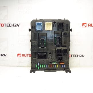
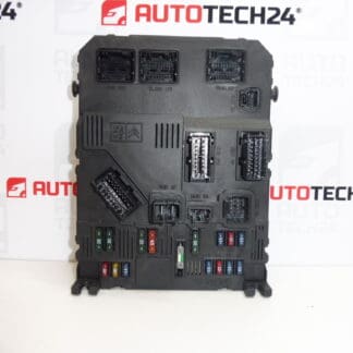
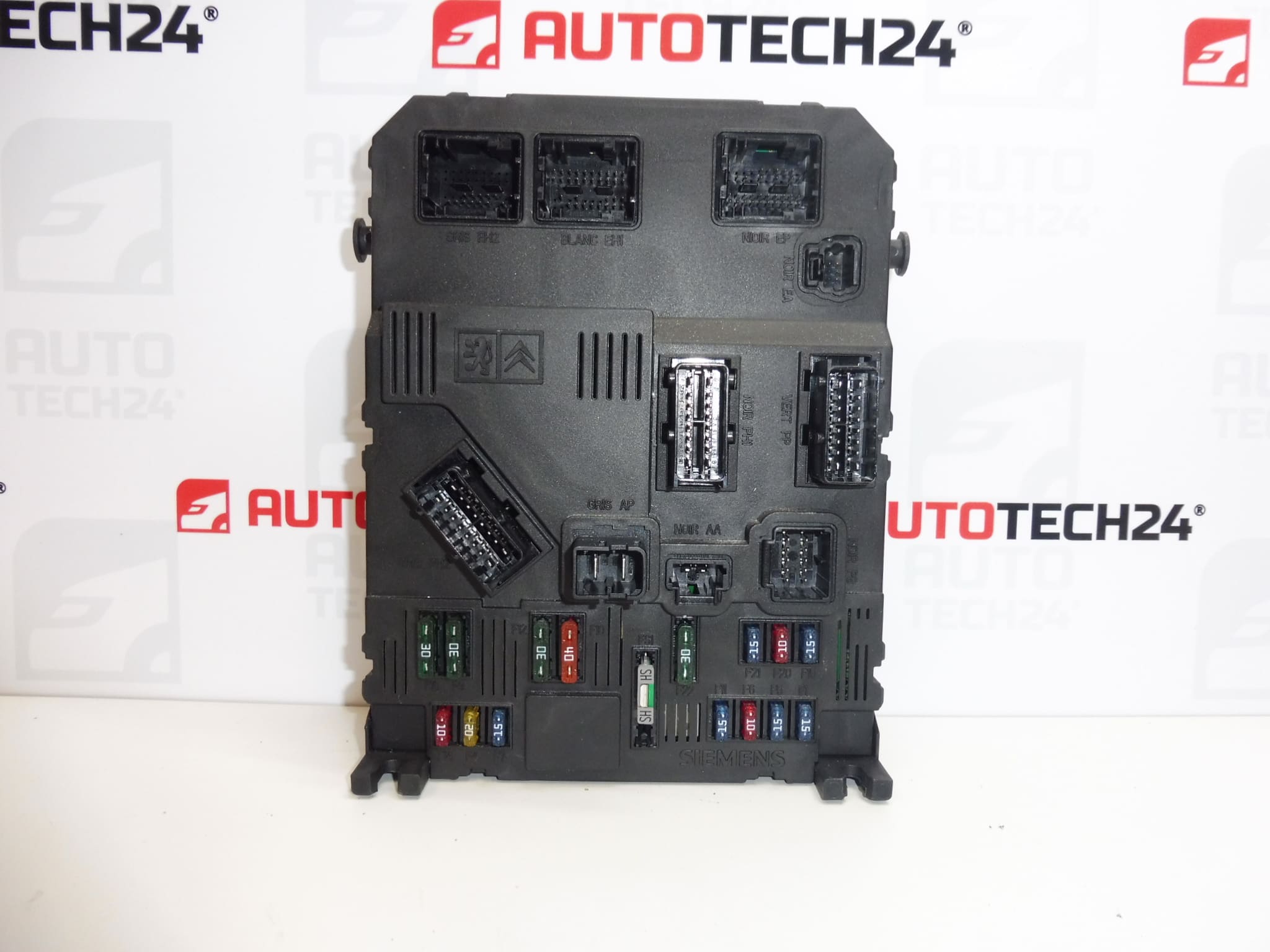
Multifunction BSI unit for PEUGEOT 206 vehicles
Part description
This used Siemens BSI E02-00 comfort control unit for Peugeot 206 is intended for vehicle electronics repairs. BSI units generally control comfort and body functions and communication between electrical systems; the specific range of functions depends on the vehicle variant and equipment.
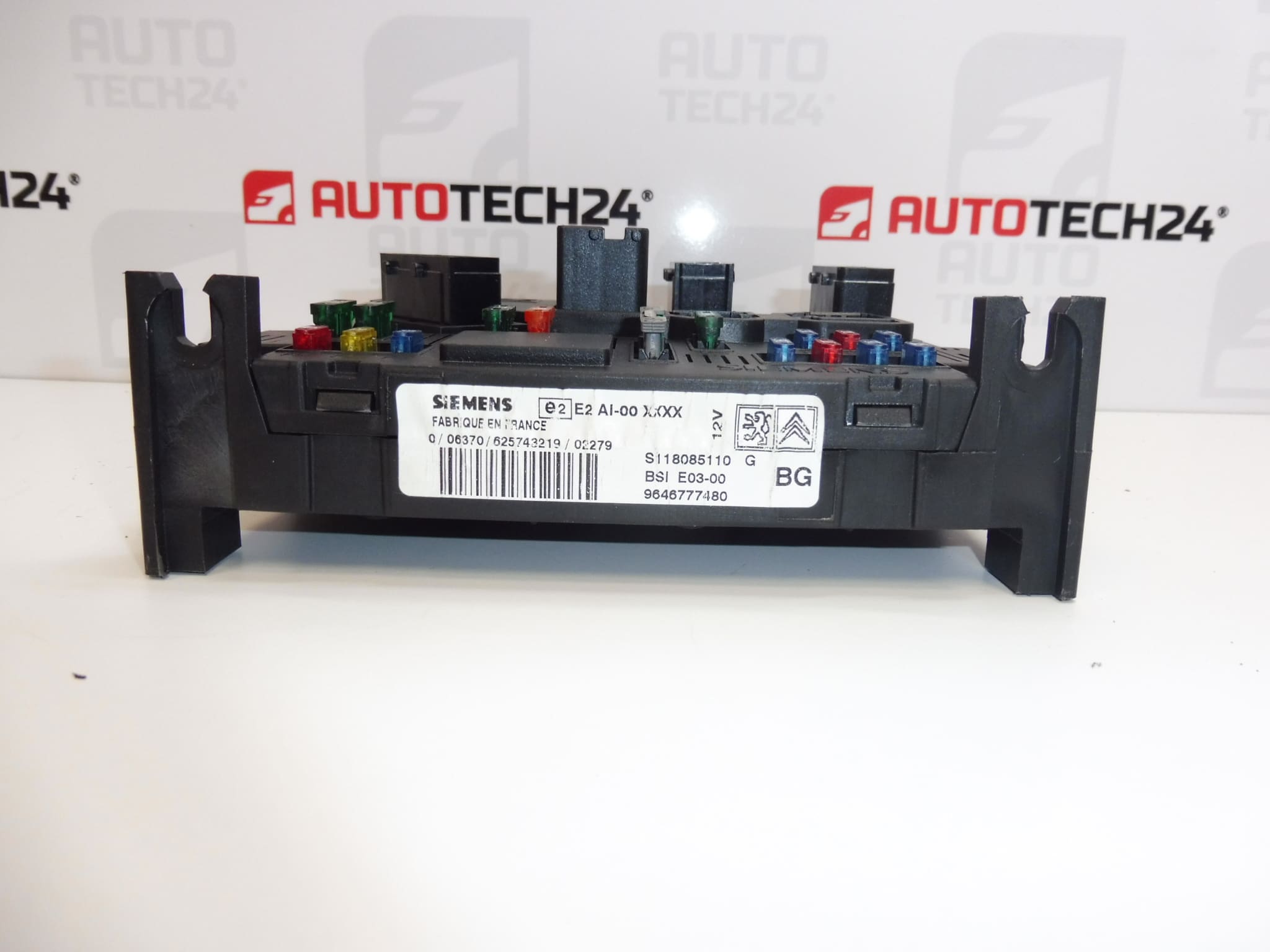
When searching for a replacement part, refer primarily to the numbers 96496777480, 1650882680 and 6580HE. Before replacement, also compare the original unit’s design, connectors and configuration requirements. A used BSI requires appropriate preparation and commissioning – simply connecting it physically is usually not enough.
Technical information
- Manufacturer: Siemens
- Model: Peugeot 206
- Part type: multifunction BSI unit / comfort control unit
- Variant designation: E02-00
- Main number: 96496777480
- Additional numbers: 1650882680, 6580HE
- Condition: used part
- Model years, engine variants and specific equipment: not specified
Product codes
- Product codes: 96496777480, 1650882680, 6580HE
- Unit designation: BSI E02-00 Siemens
- Model: Peugeot 206
The listed codes make it easier to find the part and compare it with the original unit. However, a match on a single number does not in itself replace checking the correct variant and the options for data transfer or initialization.
Installation recommendations
The following generally applies to this type of part: replacing a BSI involves not only physical installation, but also work on the vehicle’s configuration and security systems. The following procedure is general; the exact steps depend on the specific vehicle variant and the manufacturer’s instructions. Entrust data operations and coding to a specialist.
1) Before installation
- Use diagnostics to verify the cause of the fault. Similar problems can also be caused by the power supply, grounding, wiring or connectors.
- Compare the numbers, E02-00 designation, housing design, connectors and their pin layout with the original unit.
- Inspect the used unit: check for housing damage, corrosion, signs of moisture and the condition of the contacts.
- If the condition of the original unit allows it, have its configuration saved and the necessary data backed up before replacement.
- Select the commissioning method in advance and prepare the necessary keys and legitimately obtained access credentials.
2) Required tools and materials
- Standard installation tools and suitable aids for carefully releasing covers and connector locks.
- Diagnostic equipment suitable for PSA and, depending on the chosen procedure, equipment for working with the unit’s memory.
- A suitable measuring instrument, labeling materials and a clean, dry workspace with protection against electrostatic discharge.
- A stabilized power supply for programming operations, as required by the service procedure.
3) Step-by-step installation procedure
- Perform initial diagnostics and record the fault symptoms and the available configuration of the original BSI.
- Have a specialist back up the available data and confirm the suitability of the chosen method for commissioning the replacement unit.
- Switch off the ignition and electrical consumers. Follow the prescribed procedure for putting the vehicle’s electronics into sleep mode.
- Before removal, disconnect the battery according to the manufacturer’s procedure.
- Access the unit according to the service instructions. Record the wiring connections and routing.
- Release the connector locks and disconnect the connectors without pulling on the wires or using excessive force to pry them loose.
- Remove the original unit and inspect the surrounding wiring and connectors. Resolve any moisture issues or electrical faults before installing the replacement.
- Have the replacement BSI prepared by data cloning or virginization, according to the chosen method. The sequence of programming operations is determined by the service procedure used.
- Secure the unit, connect the connectors and check that they are locked in place. The wiring must not be pinched or under tension.
- Connect the battery according to the manufacturer’s instructions. Complete initialization, configuration and key adaptation according to the chosen method.
- Perform final diagnostics and verify the vehicle’s functions before refitting all removed covers.
4) Post-installation checks and test drive / functional verification
Verify communication with the unit, key recognition and the ability to start the engine. Depending on the vehicle’s actual equipment, check comfort and body functions, such as locking, lighting and wipers. Watch for unusual messages and reassess the diagnostic results after the functional test. Only carry out a test drive after successfully verifying the functions essential for safe operation.
5) Most common installation mistakes + how to prevent them
- Replacement without data preparation: arrange cloning or the initialization and key adaptation procedure in advance.
- Disconnecting electronics without following the service procedure: observe the system sleep procedure and the rules for disconnecting and reconnecting the battery.
- Power interruption during programming: use a suitable stabilized power supply and a reliable diagnostic connection.
- Forcing connectors into place: check their orientation, contacts and locking mechanisms.
- Failure to address the cause of the original fault: resolve water ingress, corrosion or wiring faults before installation to prevent damage to the replacement part.
Installation and coding – important
- The unit is used and is “paired” with the original vehicle (VIN/PIN/keys).
- Commissioning options:
- Cloning data from the old unit (EEPROM/Flash) – after cloning, the unit is plug and play.
- Virginization followed by initialization/telecoding via DiagBox (online if applicable) + key adaptation.
- It is recommended that this be carried out by a specialist with PSA service equipment (DiagBox/Lexia/PP2000).
- Always disconnect the battery before removal/installation and follow the manufacturer’s procedure to avoid damaging the unit.
Reasons why the part may become damaged
For BSI comfort control units, possible causes of damage generally include:
- Moisture and water ingress, which can cause corrosion of contacts and electronics.
- Overvoltage or improper handling of the power supply, such as an incorrect connection when jump-starting.
- Short circuits and damaged wiring, which can place stress on the unit’s output circuits.
- Mechanical damage to connectors, contacts or the housing during careless removal.
- Aging of electronic components and thermal stress.
- Improper data modifications or interrupted programming, which can render the unit inoperative even without visible damage.
These are general causes, not a description of a fault in this particular unit. Addressing the original cause of the problem is important for reliable operation of the replacement unit.