Description
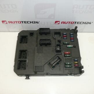
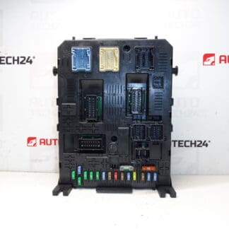
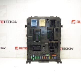
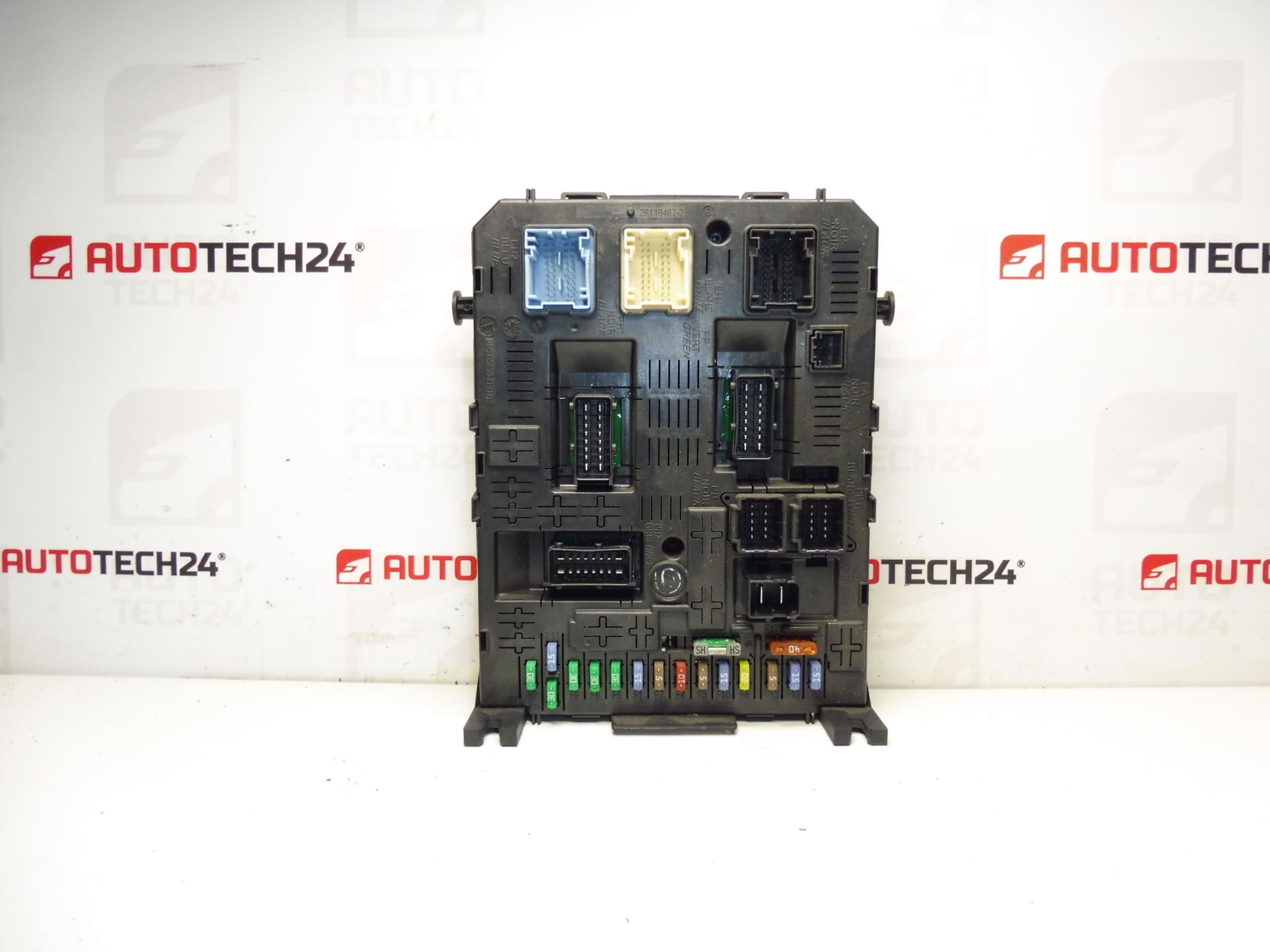
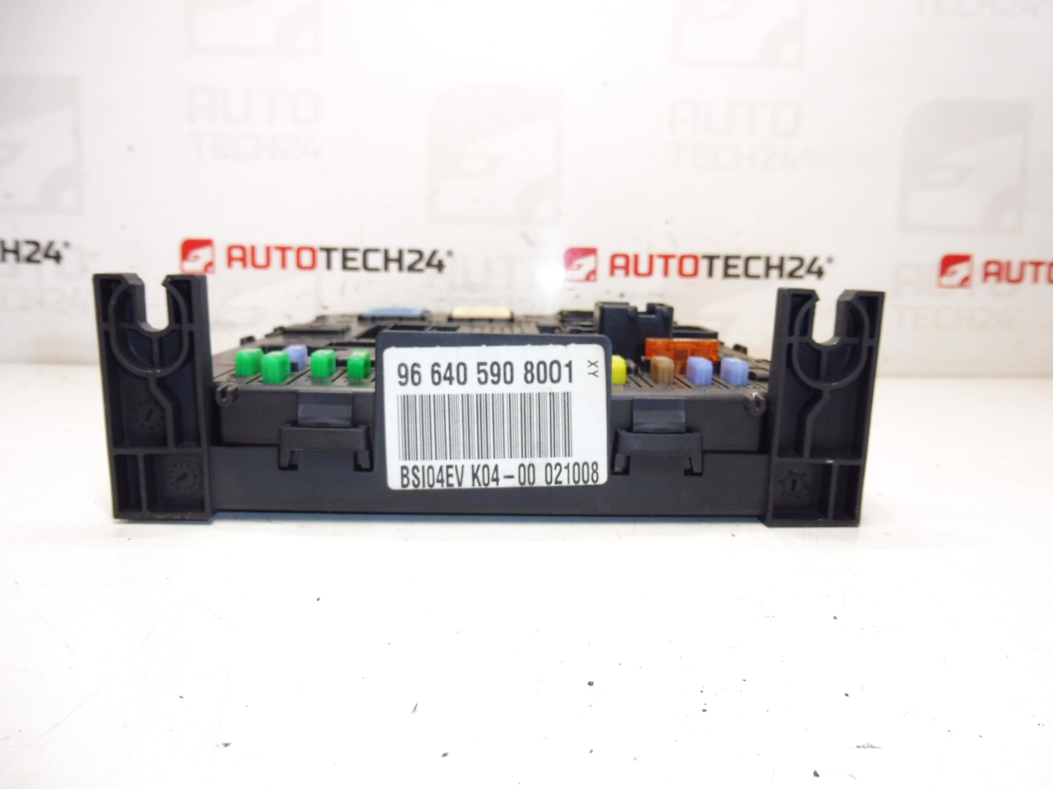
BSI BSI04EV K04-00 Johnson Controls from Peugeot 407 2008
This BSI (Body System Interface) unit BSI04EV K04-00 is a genuine control module used on Stellantis vehicles such as Citroën and Peugeot. It centralizes comfort and body electronics functions—lighting, central locking, wipers, interior electrics and communication with other control units. The unit is commonly searched by product numbers (9664059080, 6580SS, 657062, 28120836-4, 28119248-3) and is suitable for Peugeot 407 applications equipped with the BSI04EV K04-00 specification. Designed for professional workshops and experienced DIYers, this module helps restore full body-electronics functionality when the original BSI fails.
Technical Information
- Manufacturer: Johnson Controls (used on Stellantis Citroën/Peugeot)
- Model: Peugeot 407
- Product Codes: BSI04EV, K04-00, 9664059080
- Additional Numbers: 01, 6580SS, 657062, 28120836-4 (BOOT), 28119248-3 (HARD)
Function And Typical Applications
The BSI is the central comfort and body electronics control unit. It manages lighting, interior and exterior switches, central locking, wipers, alarm and communication with other ECUs. On Peugeot 407 vehicles it acts as a gateway for multiple subsystems and coordinates inputs from switches and sensors to activate relays and outputs.
How The Unit Is Replaced
- Disconnect the negative battery terminal before any work to avoid short circuits or data corruption.
- Remove lower dashboard trim panels to access the BSI module—location varies by model year but is commonly behind the glovebox or under the dash on the passenger side.
- Unplug electrical connectors carefully, release retaining clips and remove mounting screws.
- Install the replacement BSI in reverse order, ensuring connectors and grounds are clean and fully seated.
- After mechanical installation, verify functionality and read fault codes with a diagnostic tool. Programming or synchronization of the immobilizer/keys may be required using manufacturer-level diagnostics (e.g., DiagBox/Lexia) to restore full vehicle communication.
Installation Recommendations
- Always Disconnect Battery And Observe ESD Precautions: Protect the module from static discharge and avoid handling circuit board contacts.
- Mark Connectors And Take Photos Before Removal: Helps ensure correct reconnection and reduces reassembly time.
- Check Fuses And Ground Points: Failures are often accompanied by blown fuses or poor grounds—inspect and rectify before fitting a new module.
- Use A Diagnostic Tool After Fitment: Clear fault codes, run actuator tests and, if needed, perform key/immobilizer synchronization or BSI coding with manufacturer-level software.
- Avoid Powering The Unit With Loose Connectors: Ensure all connectors are fully engaged before reconnecting the battery.
Why This Part Most Commonly Fails
- Moisture Ingress And Corrosion: Water leaks or condensation can corrode connector pins and PCB tracks.
- Electrical Surges And Poor Battery Connections: Voltage spikes or unstable power supply damage internal electronics.
- Connector Wear And Vibration: Repeated vibration or loose connectors cause intermittent faults or broken contacts.
- Age-Related Electronic Component Degradation: Over time relays, capacitors and solder joints can fail, especially in high-heat environments.
This BSI unit is ideal for mechanics and experienced DIYers who need an original-spec control module for Peugeot 407 vehicles using the BSI04EV K04-00 variant. Verify the product and additional numbers listed in the Technical Information to ensure correct fitment for your vehicle before installation.