Description
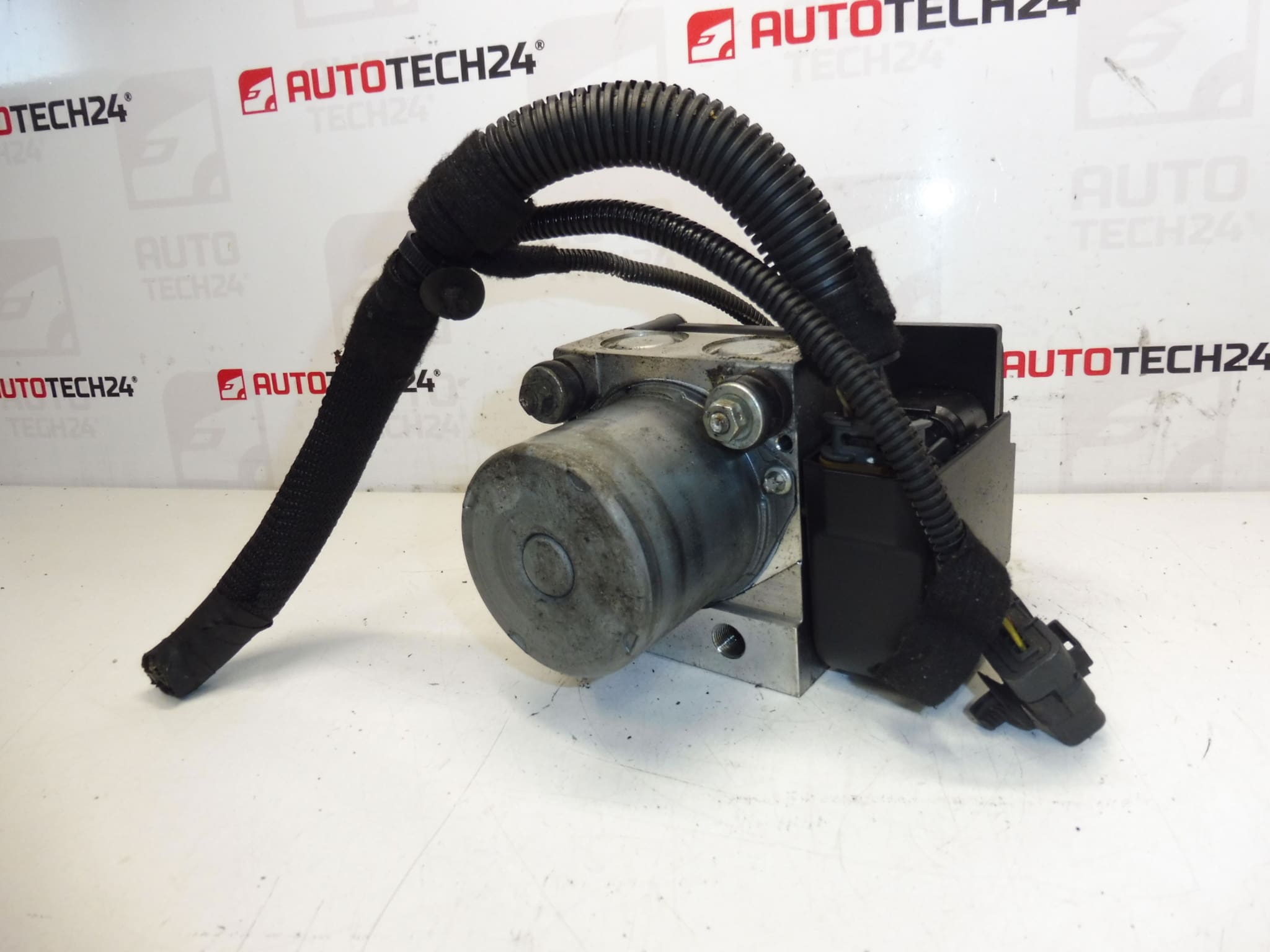
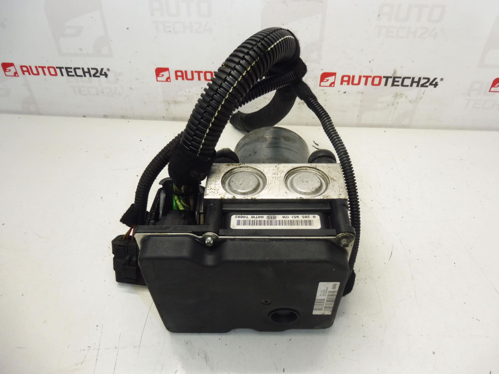
Control module, ABS and ESP pump, hydraulic block PEUGEOT 308. Tested, fully functional. With a piece of wiring.
This Bosch ABS/ESP hydraulic unit is a direct-fit component for Peugeot 308 vehicles and is commonly searched by its part numbers (0265951176, 9667055880, 4541QJ). The unit integrates the electronic control module, hydraulic pump and valve block responsible for anti-lock braking and electronic stability control. Supplied with a section of wiring harness, it is an efficient replacement option for workshops and DIY mechanics who need to restore ABS and ESP functionality quickly.
Technical Information
- Manufacturer: Bosch
- Model: Peugeot 308
- Product Codes: 0265951176, 9667055880, 4541QJ
- Additional Numbers: 4541QK, 1682607680, 0265251442, 9666957480
Compatibility
Designed for Peugeot 308 vehicles. Buyers frequently locate this part by one of the listed product codes; verify the part number against your vehicle’s paperwork or service documentation before installation.
Function And Symptoms Of Failure
The ABS/ESP hydraulic block modulates brake pressure to prevent wheel lockup and to assist vehicle stability control during braking and emergency maneuvers. Typical symptoms of a failing unit include persistent ABS or ESP warning lights on the dashboard, reduced ABS function (longer stopping distances under heavy braking), pulsating brake pedal at normal speeds, unusual pump noises or intermittent loss of traction control.
Common Causes Of Failure
- Corrosion And Moisture Ingress: Brake fluid contamination or water entry can corrode valves and electrical connectors.
- Electrical Faults: Damaged wiring, connector corrosion or internal electronics failure can interrupt communication with the ABS ECU.
- Hydraulic Wear And Blockage: Debris or degraded brake fluid can clog valves and damage the pump motor.
- Accident Damage: Impact can bend or damage the unit and associated lines.
- Aging And High Mileage: Mechanical wear over time reduces reliability.
Installation Recommendations
Before starting work, always consult factory repair literature for vehicle-specific procedures. General replacement steps:
- Disconnect the negative battery terminal to prevent electrical damage.
- Safely raise and support the vehicle and protect paintwork from brake fluid.
- Depressurize the brake system as specified by the manufacturer.
- Disconnect electrical connectors and remove hydraulic brake lines (capture fluid and cap lines to avoid contamination).
- Unbolt and remove the ABS/ESP unit. Install the replacement, torque fasteners to specification and reconnect lines and wiring.
- Bleed the brake system thoroughly. For full ABS pump priming and removal of air from the hydraulic circuit, use a diagnostic tool capable of running the ABS bleed/activation routine where available.
- Clear fault codes and verify system operation using a suitable diagnostic scanner. Test drive to confirm stable braking and ESP operation.
Recommendation: If you do not have the appropriate diagnostic equipment, have the vehicle checked and the unit commissioned by a workshop with ABS diagnostic capability. Always replace any damaged seals or brake hoses and use fresh, manufacturer-specified brake fluid.
Why This Part Is Often Replaced
The ABS/ESP unit is exposed to harsh conditions (heat, moisture, contaminated fluid) and combines hydraulic and electronic components, so failures are relatively common after high mileage or following coolant/brake fluid contamination and road-salt corrosion. Accidents that deform suspension or body structures can also damage the hydraulic block or its connectors.
Included In Delivery
Hydraulic block with electronic control module and a piece of wiring harness as pictured/described in the listing. Refer to the product codes listed above for exact fitment.